From information in the patents and technical documentation written by Stan Meyer, it is clear that the Voltage Intensifier Circuit (VIC) is the key to Meyer’s claim of deriving oxyhydrogen gas from water while consuming almost no power. According to Meyer, this effect can best be achieved by constructing an asymmetric capacitor made from stainless steel tubes arranged co-axially using water as a dielectric and subjecting the water to a very specific cycle of energization.
The VIC is a tuned circuit built around this “water capacitor” designed to operate at electrical resonance when energized by a series of square wave pulses.
Energy pulsed into the capacitor produces resonate oscillations with the inductors placed around it leading to high voltage potentials between these components.
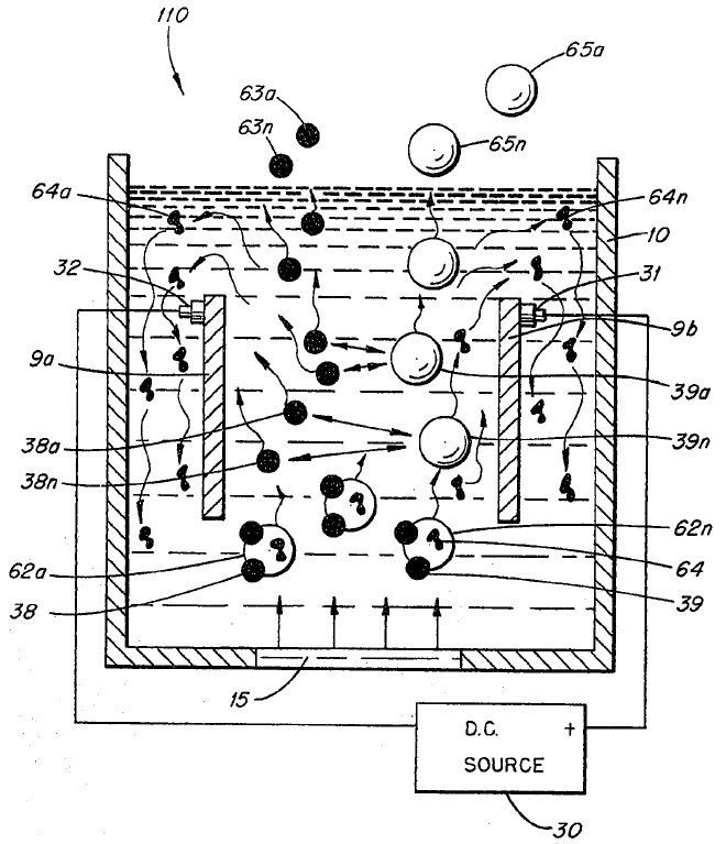
According to Meyer, the elevated potentials across the water capacitor’s plates exert a polarizing electrostatic force on the water in between. Under certain amp-restrictive effects manifested by the VIC, the magnitude of this polarizing force can reach levels sufficient to overcome the strength of covalent bonding between water’s Oxygen and Hydrogen atoms. In this way, Meyer claimed that the VIC operates to result in the abundant production of Hydrogen and Oxygen gases yielded in stoichiometrically optimal ratio for combustion as a clean burning fuel.
The most important feature of the VIC is that it prevents the capacitor from discharging during the time between pulses. In other words, the charge stored within the capacitor is prevented from discharging when the power to the primary coil of transformer Pri/L2 is switched off. Since capacitve discharging is not allowed to occur, the result in an “intensification” of the voltage felt by the water molecules within during each successive pulse.
I and my research partner, Russ Gries (http://rwgresearch.com), have long been working together to understand and replicate Meyer’s technology. What follows is an illustrated sequence reflecting our present understanding and working theory of the operation for Meyer’s Voltage Intensifier Circuit.
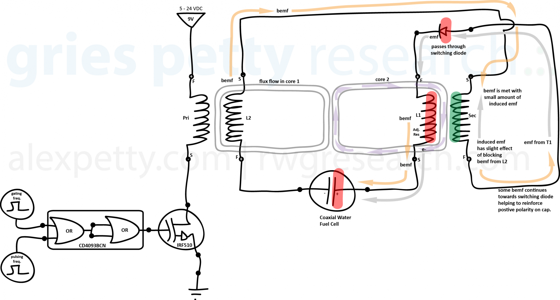
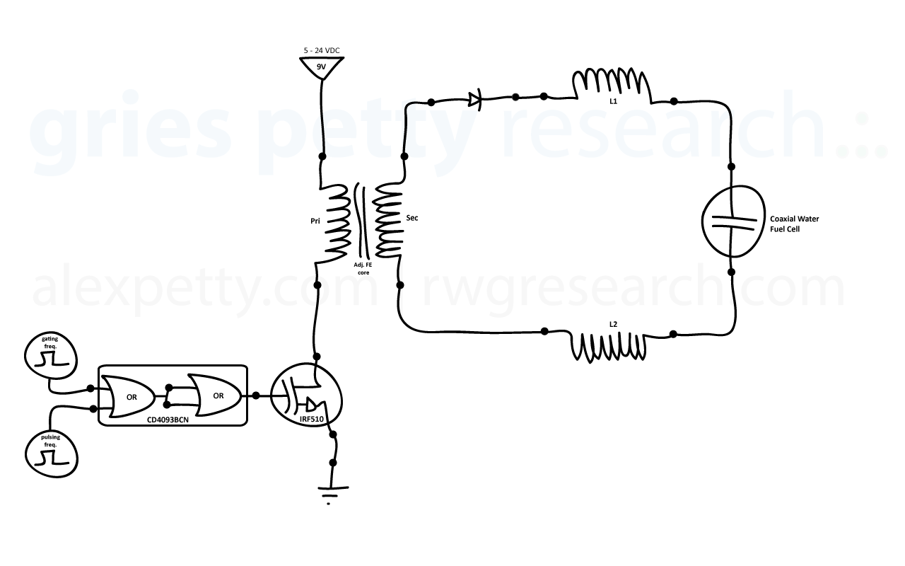
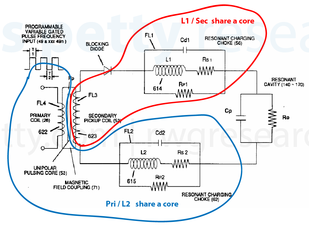
The standard VIC schematic, which is included in all of Meyer’s WFC related patents, is shown on the right side of the drawing below.
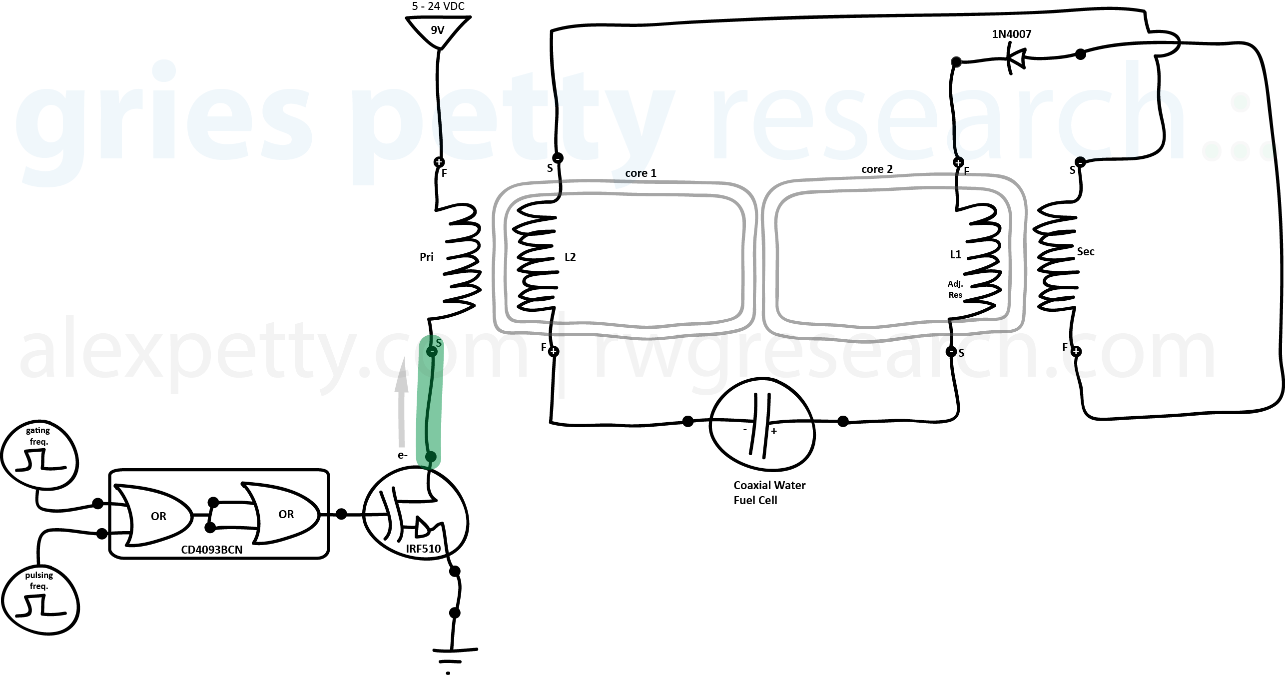
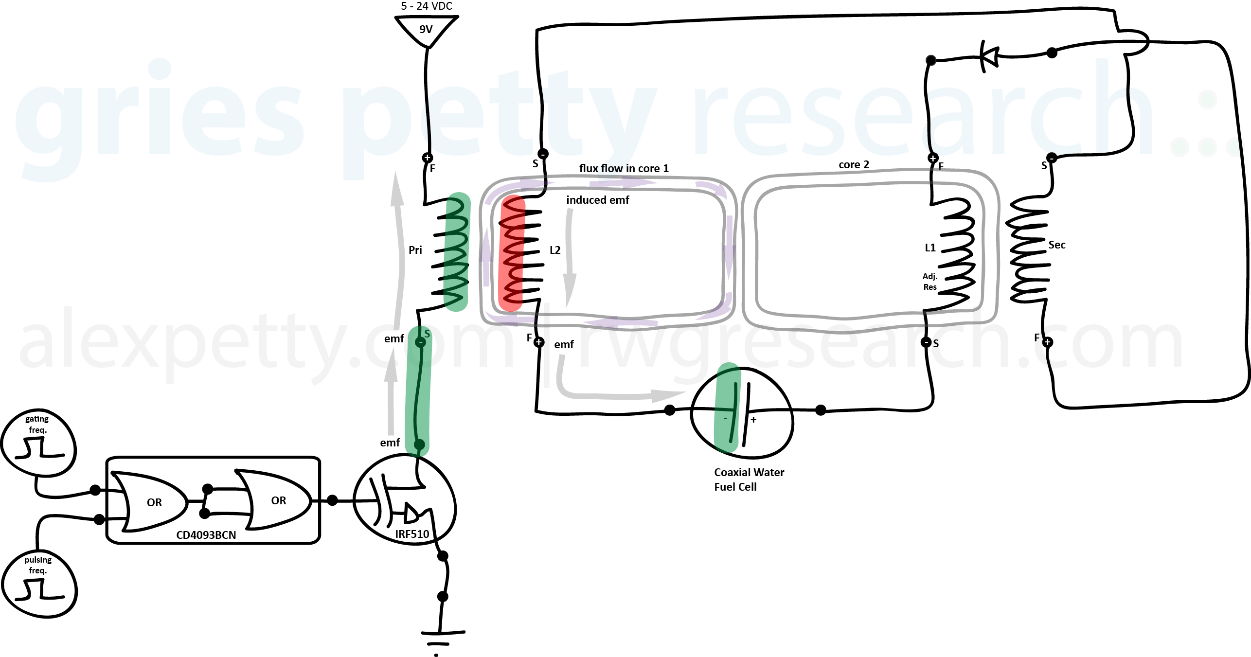
Based on the results of our research to this point, we see that an equivalent way to draw the VIC is as follows:
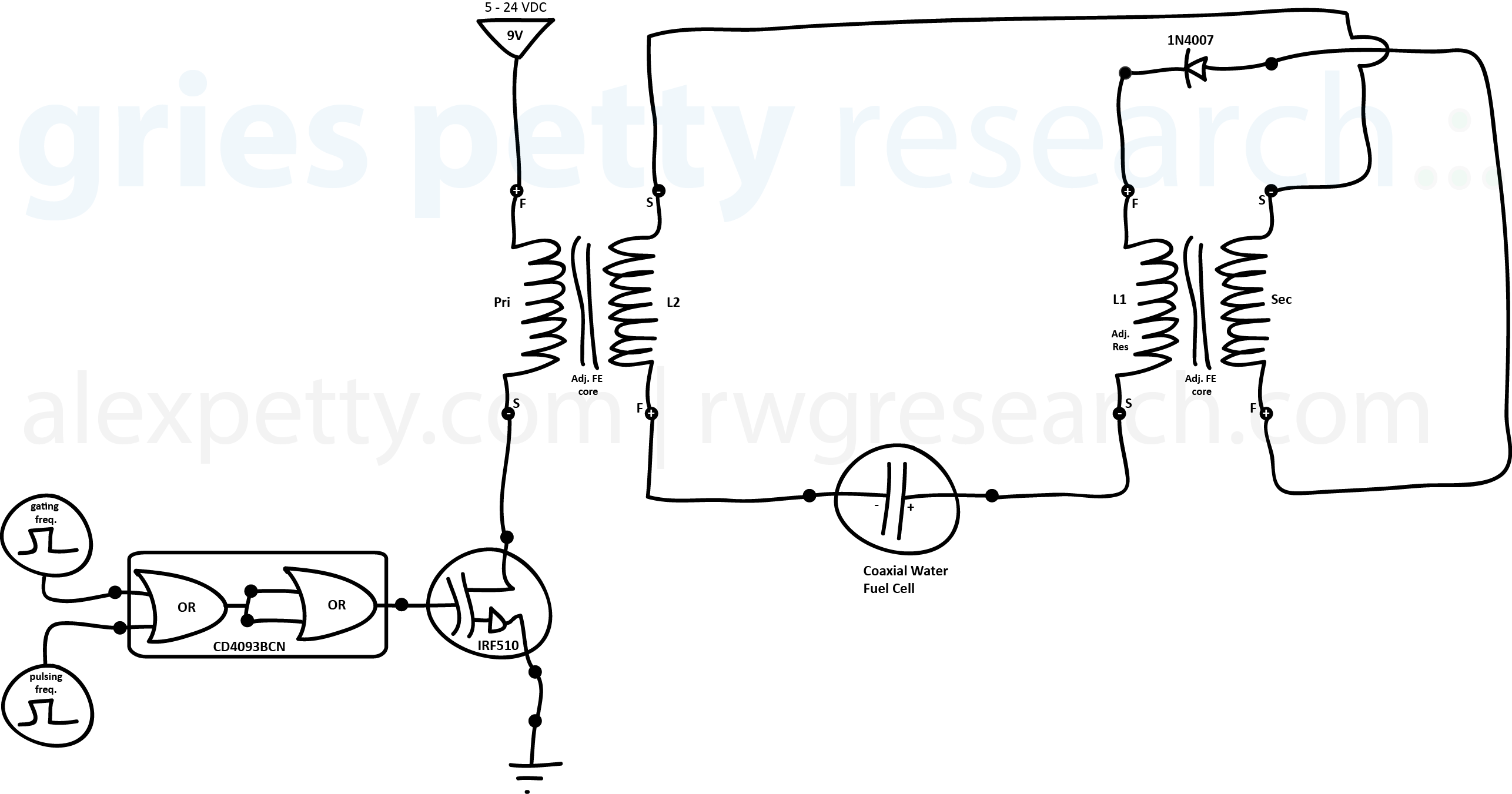
We see that this arrangement much better accounts for the various effects described in Stan Meyer’s technical writings.
In this writing, the term T1 will be used to refer to the time period during which the pulse is being applied to the primary of the transformer Pri/L2 (pulse-on).
T2 will be used to refer to the time period during which the pulse is no longer being applied to the primary of the transformer Pri/L2 (pulse-off).
T3 will be used to refer to the period of “off-time” where the pulses are gated.
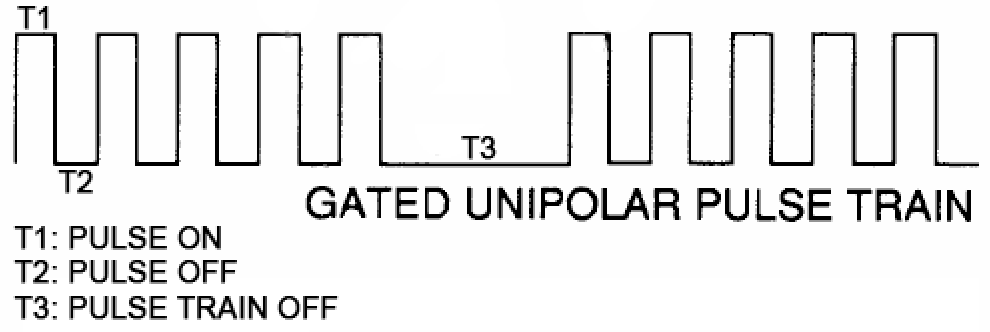
Pulses applied to the primary side of step-up transformer Pri/L2 during T1 result in pulses of charge being driven into the cathode of the water capacitor.
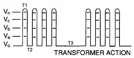
Since the VIC is designed to promote step-charging within the water capacitor, each successive pulse will yield an incrementally higher charge amplitude. I will refer to these incrementally increasing amplitudes using Meyer’s Vo through Vn notation.
During T1, as the inductors in the VIC are energized, they produce magnetic fields.
When T1 pulse turns off, these magnetic fields collapse producing BEMF charge pulses. The result is a doubling of the frequency of pulses experienced by the water capacitor.
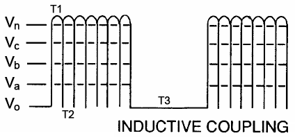
With each pulse, the charge stored in the water capacitor builds up amplitudes v0 through Vn.
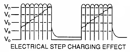
As charge amplitude within the water capacitor reaches the Va to Vb range, the VIC’s “mode of operation” changes. This operational change in the VIC causes the water capacitor to be further unable to relax its stored charge during T2, despite mounting charge pressures in the water capacitor.
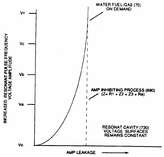
Meyer referred to the effects which bring about this operational change in the VIC as the “Amp Inhibiting Process” which is enabled by the “Electron Bounce Phenomena”. I will describe these concepts in detail later in this writing.
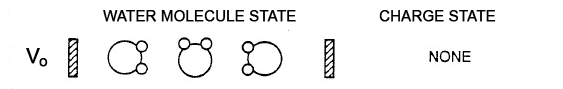
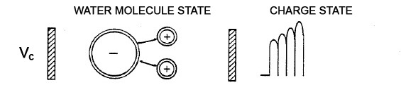
In the initial condition (Vo), the circuit is turned off. At this point, there is no voltage applied to the VIC. There is no charge stored within the water capacitor. There is no alignment by polarity of the water molecule within the water capacitor.
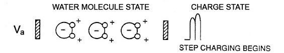
As charge amplitude in the water capacitor reaches (Va), the water molecules begin to experience alignment by polarity in the capacitor’s electrostatic field. In this field, water’s Oxygen atoms are pulled towards the capacitor’s cathode while Hydrogen atoms are pulled towards the anode.
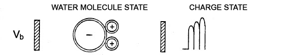
As charge amplitude on the water capacitor reaches (Vb), water molecules begin to be strongly oriented by polarity in the capacitor’s electrostatic field.
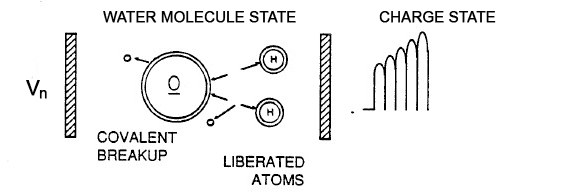
As charge amplitude on the water capacitor reaches (Vc), water’s covalent bonds between it’s Hydrogen and Oxygen atoms begin to feel a sheering stress.
As charge amplitude on the cell reaches (Vn), the covalent bonds which bind Hydrogen and Oxygen together are broken and oxyhdrogen gas is produced by the water capacitor.
Let’s now take a closer look at the operation of the VIC through a series of illustrations.
Pulsing from Vo to Va
Several pulses (instances of T1) occur to bring the cell from Vo to Va.
Vo + Step 1
T1 begins.
The input waveform is applied to the gate of the MOSFET which in turns allows current to surge towards the Primary side of the transformer Pri/L2.
Vo + Step 2
T1 continues.
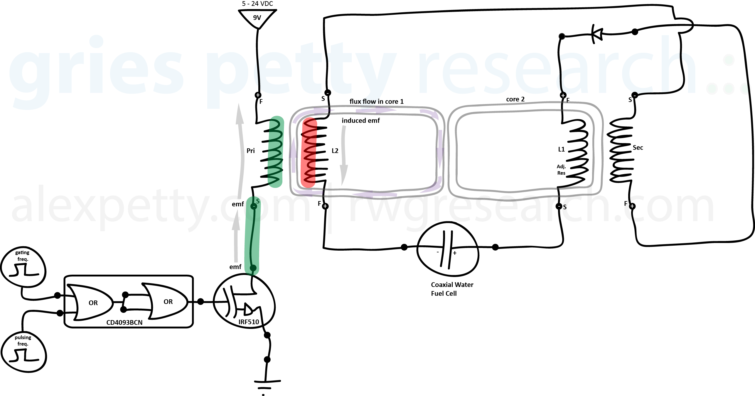
The current reaches the Primary side of transformer Pri/L2 and produces a magnetic field on this primary coil. The magnetic field from the Primary coil induces an opposite charge flow on the L2 coil.
Vo + Step 3
T1 continues.
The induced current from L2 flows to the water capacitor and charges it’s cathode.
Vo + Step 4
T1 continues.
As the water capacitor’s cathode becomes charged, it’s anode develops an equal and opposite charge (in accordance with the nature of asymmetric capacitors).
As the capacitor’s anode charges, a displacement current arises and begins flowing from the anode towards transformer L1/Sec.
The current flowing from the anode of the capacitor reaches coil L1 and there produces a magnetic field.
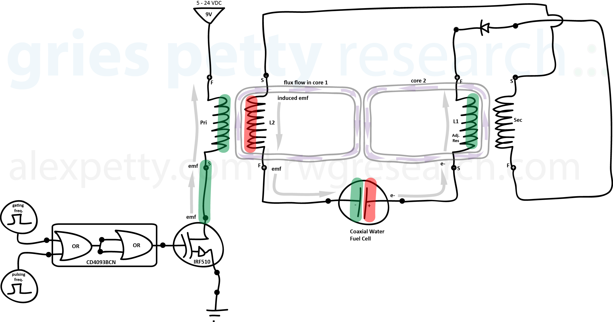
Vo + Step 5
T1 continues.
The magnetic field of coil L1 induces an opposite charge flow in the Secondary coil. This induced current flows towards the open (or “switched on”) side of the diode.
At the same time, the charge flowing through coil L1 continues towards the diode where it is blocked from proceeding further.
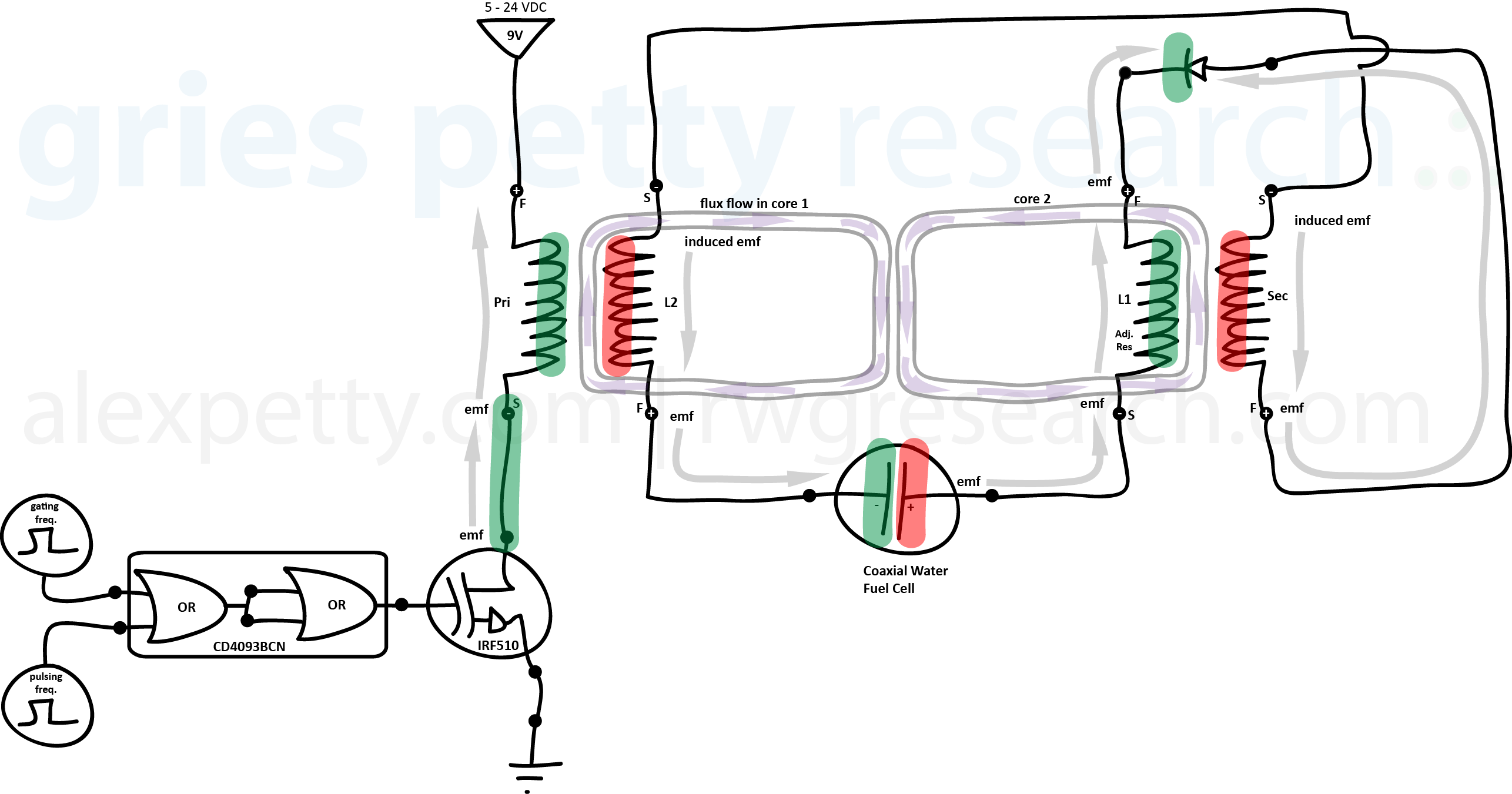
Vo + Step 6
T1 ends.
T2 begins.
With the pulse turned off, the magnetic field in coil L1 collapses sending a positive “frequency doubling” BEMF pulse into the anode of the water capacitor.
The induced charge from the secondary coil flows through the “switching” diode into coil L1 from the opposite direction. The polarity of this charge flow helps to preventing the capacitor from discharging.
The magnetic field in coil L2 also collapses sending a BEMF pulse to the negative terminal of the secondary coil. The polarity of this pulse also contributes to preventing the capacitor from discharging however.

Vo + Step 7
T2 ends
T1 begins again.
The process above is repeated for each pulse in the sequence until charge amplitude Va is reached.
Note that the starting voltage at the outset of each pulse (T1) is higher then the previous pulse because the VIC does not allow the capacitor to discharge between pulses. Up to this point, it has done this as a result of the various sources of positive voltage it has sent through the switching diode during pulse off time (T2).
Pulsing from Va to Vb
By this time, several rounds of T1 and T2 will have occurred bringing the the water capacitor’s stored charge amplitude from Vo to Va. During these first few pulses, the pulse frequency must be fine-tuned for peak resonance and impedence matching. Impedance matching for the VIC is given by equation:
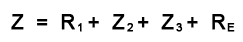
Where:
(R1) is the resistive value of the secondary pickup coil (52) plus the magnetic field strength of primary coupling field (71) in direct relationship to inductance field strength (Rp). Rp is determined by the number of turns of wire that make up secondary coil (52).
(Z2) is determined by inductance field strength (FL1) and resistive values (RS1) of coil (56)(L1) when exposed to magnetic coupling field (Rp).
(Z3) is determined by inductance field strength (FL2) and resistive values (RS2) of coil (62)(L2) when exposed to magnetic coupling field (Rp).
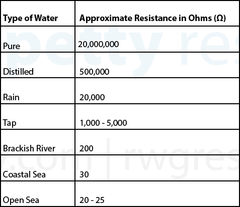
(RE) is the ohmic resistance presented by the water between the capacitor’s plates1. This resistance value is dependent on the degree of contaminates the water contains. For example, owing to distillation that occurs during the evaporation phase of the water cycle, rain water contains contaminates less then 20 ppm and so has a fairly high resistivity of around 20,000 Ohms.
When the VIC has been so-tuned, just after reaching Va, the ciruit begins to exhibit additional amp-inhibiting characteristics with the onset of the Electron Bounce Phenomena.
Electron Bounce Phenomena
All of the inductors in the VIC are wound in the same direction and the movement of magnetic flux through the cores is everywhere reinforced during pulse-on time (T1). Said another way, each pulse applied to the Primary is felt through inductive coupling by L2 and, by extension, L1 and the Secondary.
During step charging, if the impedance of the input is matched continuously with the impedance of the water capacitor and coils L2/L1, electrons associated with the copper material composing the magnet wire of L2 and L1 become subject to the force of the magnetic field coupling.
This is particularly important at L2.
Meyer claimed that when the strength of the magnetic field coupling between the Primary and L2 is sufficiently high, electrons from the magnet wire’s copper atoms are dislodged and begin to “cluster” on the positive terminal of L2. This has the effect of temporarily changing the polarity of the postive terminal of L2 to negative. At the same time, postively charged copper ions (having just lost their electrons) move towards the negative terminal of L2. This temporarily changes the polarity of the negative terminal of L2 to positive.
(Note: In the drawing below, I added the “L2” identifier to the secondary pickup coil label. I did this to reinforce that we are considering L2 to be the coil sharing a core with the primary.)
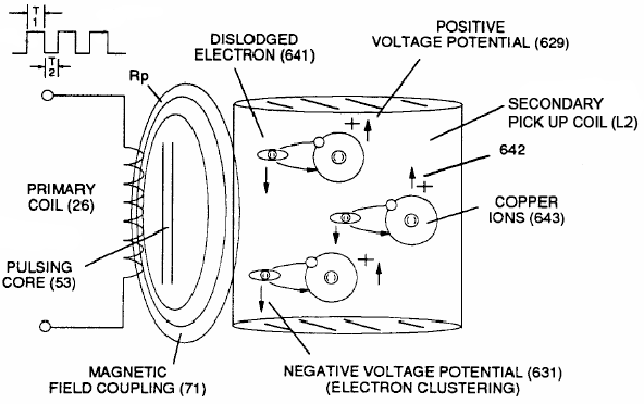
The effect reverses the polarity of L2 during pulse-on time causing induced current at L2 to flow around the circuit in the opposite direction during T1. This sees the VIC function quite differently, in a mode that further prevents capacitive discharge by confining the flow of current during T1 to movements internal to the coil thus inhibiting current flow elsewhere in the circuit.
The matched impedance (at resonance) also causes mutual inductance to transform the internal capacitance of L1 and L2 into a coherent voltage potential equaling the sum of all minute potentials stored electrostatically within the coils. This too contributes to pushing voltages towards Vn.
As the pulse is turned off (T2) and L2 is de-energized, dislodged electrons reassociate themselves with the positively charged copper ions and returns the magnet wire again to a neutral net electrical charge. This stabilizing charge movement displaces the opportunity for capacitive discharge during T2.
The cycle of T1 and T2 is repeated until the span of T3 is reached at which point the capacitor is allowed to discharge.
Then the entire process is then repeated.
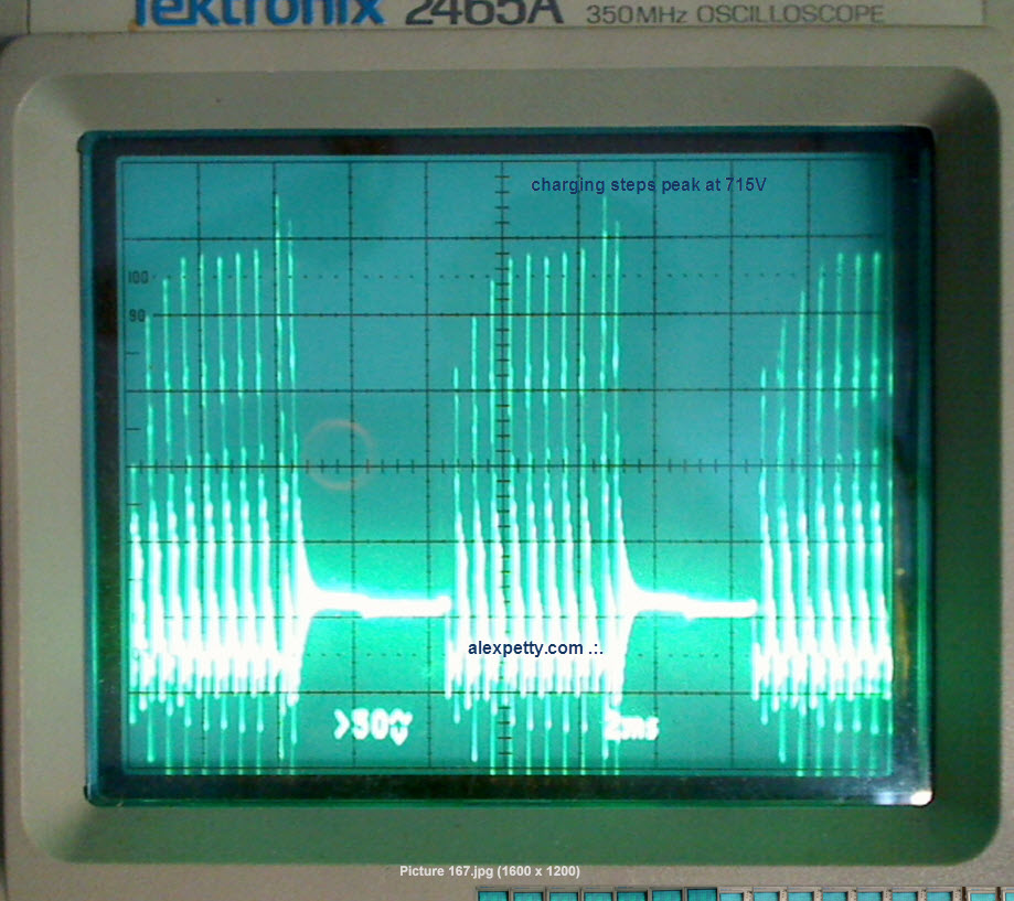
Scope-shots
The input waveform is applied to the gate of the MOSFET.
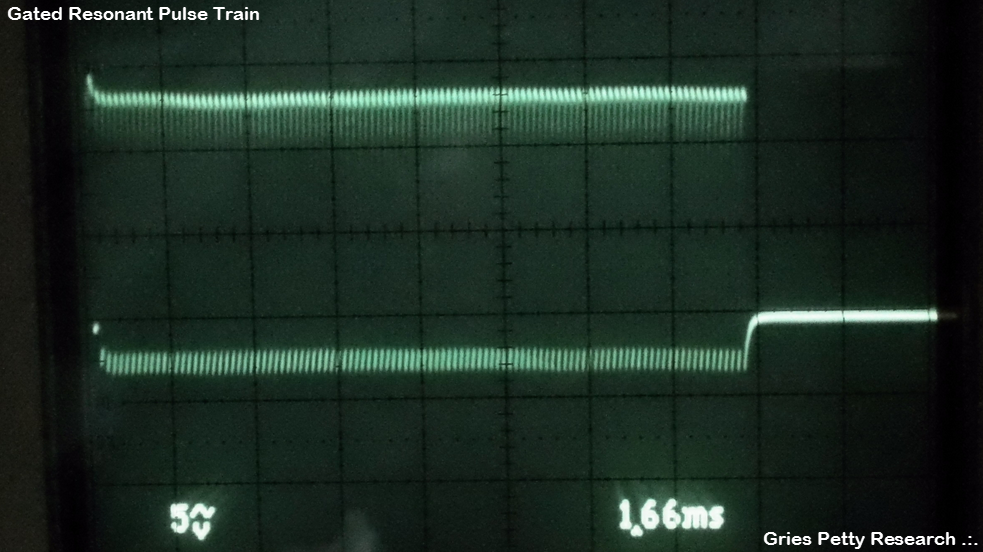
In the scope-shot below, the top trace is on the negative terminal (Vss) of the primary coil of transformer Pri/L2. The bottom trace is on the MOSFET gate.
This scope-shot shows the primary coil’s magnetic field bulding during T1 as the voltage amplitude steadily increases on the coil. At the onset of T2, the field collapses and high amplitude BEMF oscillations move back towards the MOSFET.
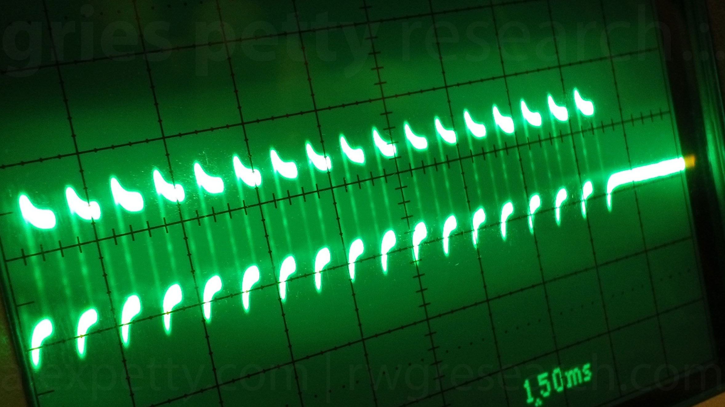
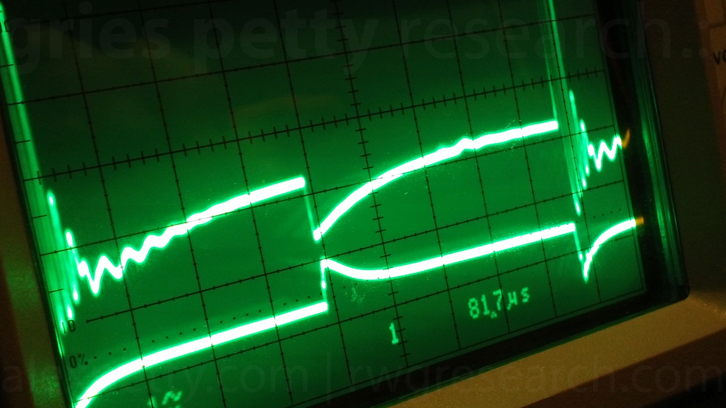
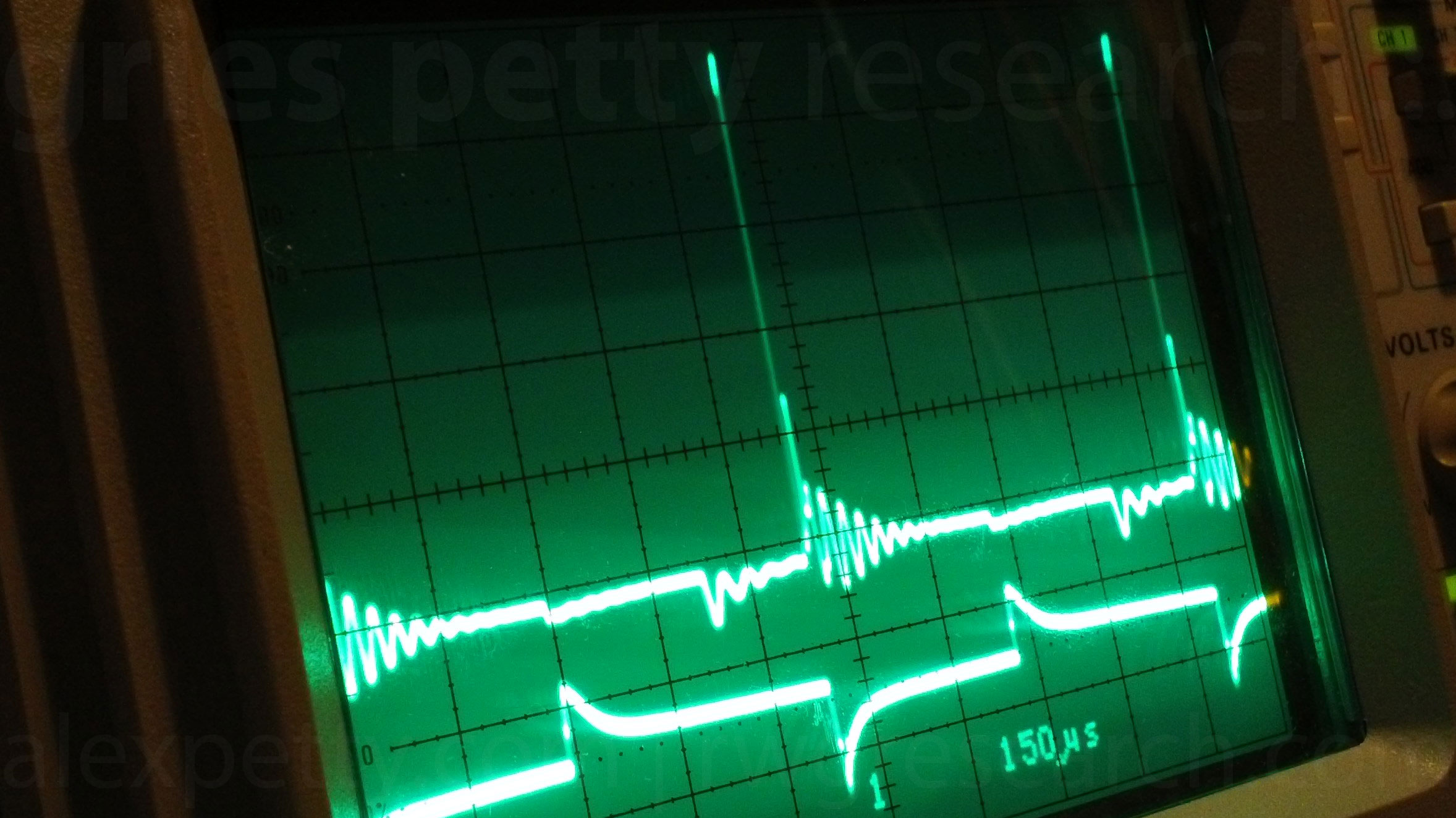
In the scope-shot below, the top trace is between the positive terminal (Vdd) of L2 and the negative terminal (Vss) of the water capacitor. The bottom trace is on the MOSFET gate.
This scope-shot shows the capacitor charging as T1 begins.
1. From T1 + 0μs to T1 + ~160μs, the capacitor charges. (Vo + Step 3)
2. During this charging time, a displacement current proceeds to L1 and energizes the coil. A magnetic field is formed from T1 + ~10μs to T1 + ~220μs (Vo + Step 4)
3. At T1 + ~220μs, a ripple occurs when the charge flow hits the blocking diode. (Vo + Step 5)
4. At T1 + ~350μs, T1 ends and the magnetic field of L1 collapses sending high amplitude BEMF oscillations back into the water capacitor. (Vo + Step 6)
Note that the oscillations from the collapse of L1 and those from the collapse of L2 are phase shifted by ~20%.
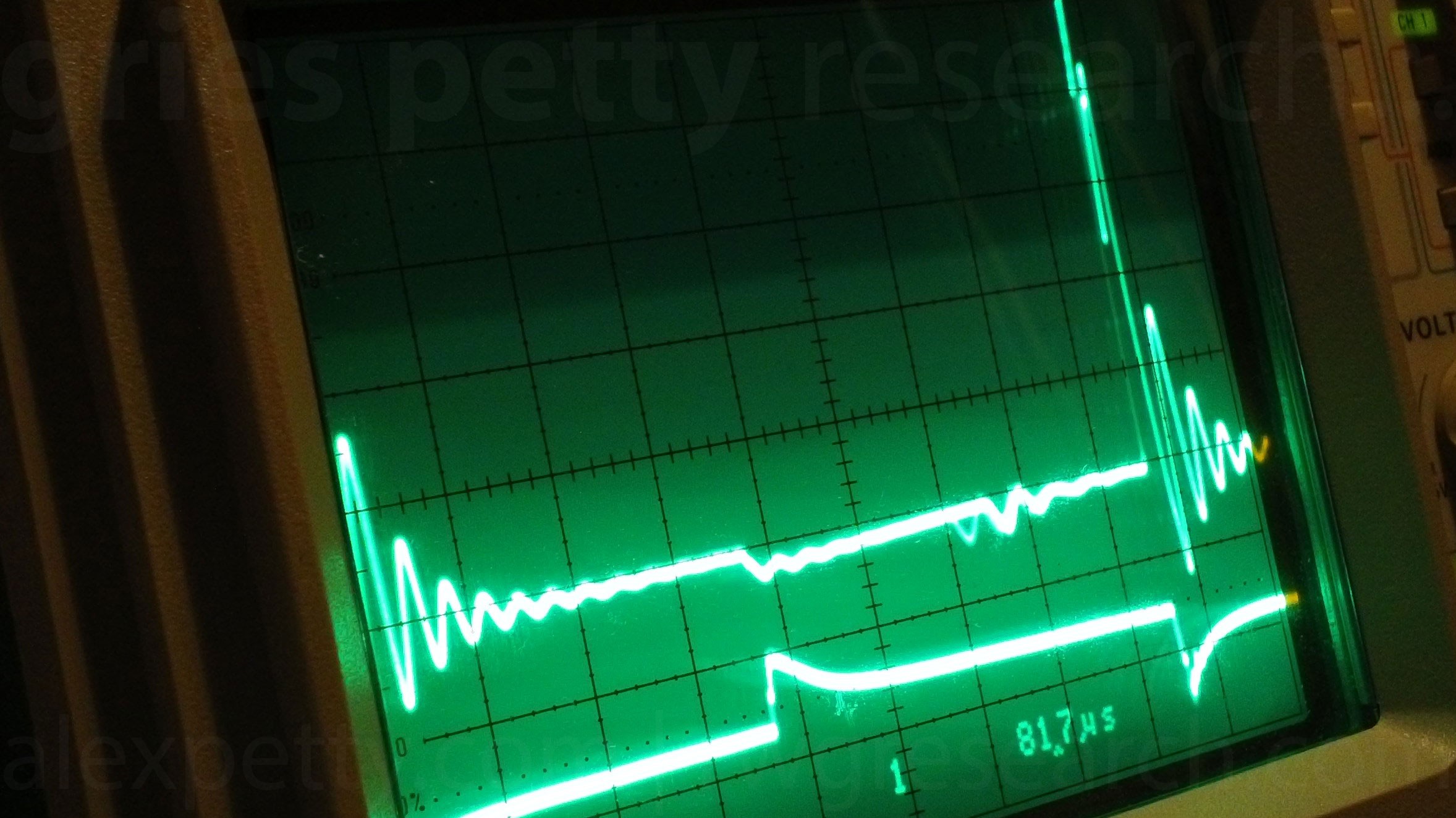
In the scope-shot below, the top trace is between the positive terminal (Vdd) of the water capacitor and the negative terminal (Vss) of L1. The bottom trace is on the MOSFET gate.
This scope-shot is very similar to the trace taken from the water capacitor’s cathode, though the charging of the capacitor is not quite as pronounced when the probe is on the anode. The polarity of the waveform is identical across the capacitor (and through the water in between).
I changed the time and voltage scales a bit in this shot so that the charging up of the cap, the coil and the diode ripple could be seen a little more clearly.
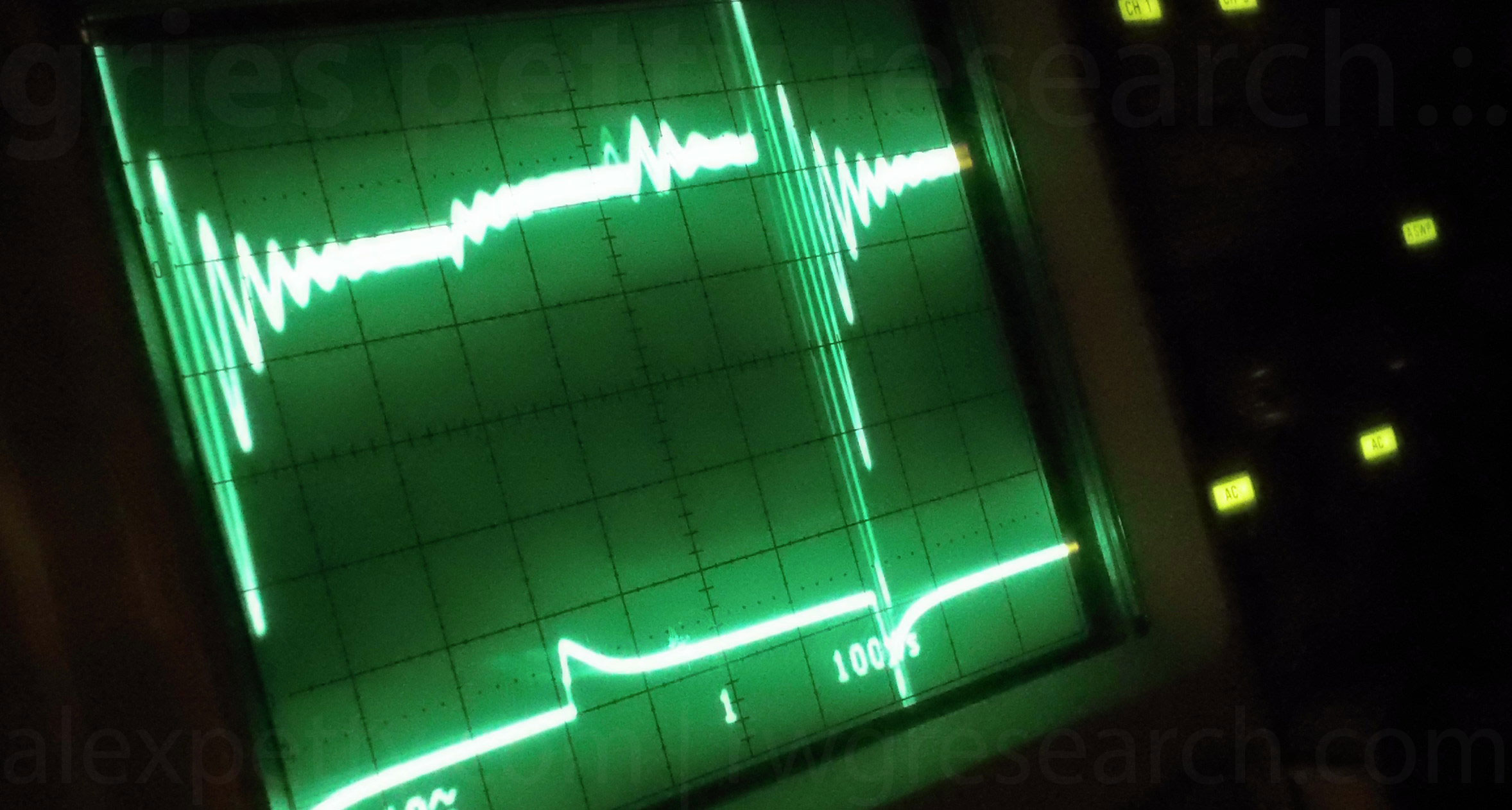
In the scope-shot below, the top trace is between the positive terminal (Vdd) of L1 and the cathode of the diode. The bottom trace is on the MOSFET gate.
This scope-shot shows the capacitor charging as T1 begins.
1. From T1 + 0μs to T1 + ~200μs, the amplitude of the wave form increases as the water capacitor and magnetic field in L1 charge. (Vo + Steps 3 and 4)
2. At T1 + ~220μs, the charge, having passed through L1 is blocked by the diode producing a ripple in the waveform. When the diode is removed from the circuit, no ripple occurs. (Vo + Step 5)
3. At T1 + ~350μs, T1 ends and the magnetic field of L2 collapses driving high amplitude BEMF oscillations around into the Secondary coil and further. (Vo + Step 6)
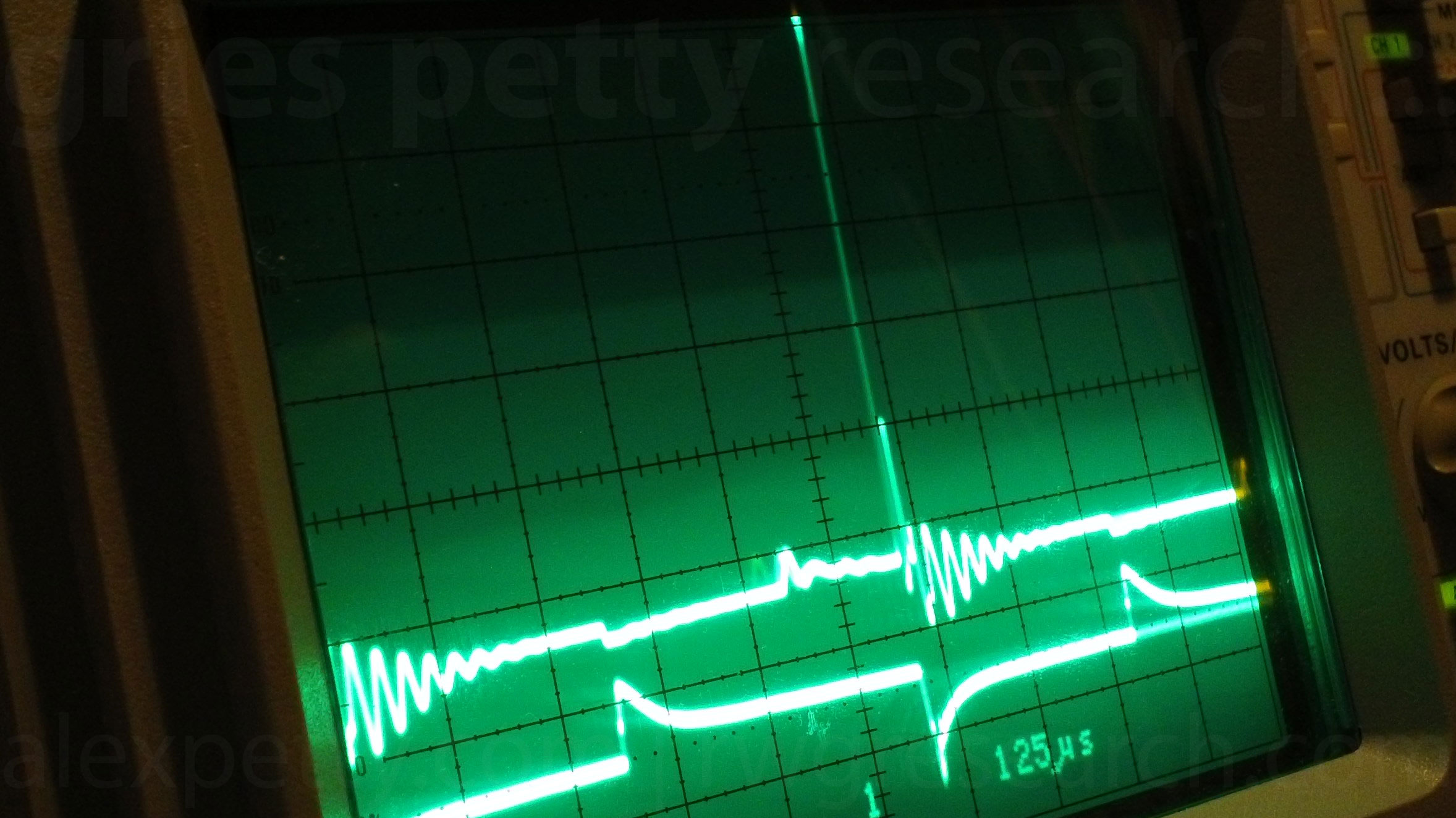
In the scope-shot below, the top trace is between the anode of the diode and the positive terminal (Vdd) of the secondary. The bottom trace is on the MOSFET gate.
Here the polarity of the ripple is reversed and the ringing is in phase with the ringing of L2.
We are currently working to verify the charge and flux path sequence during the Electron Bounce Phenomenon portion of the circuit’s operation, so please stay tuned.
Alex .:. & ~Russ
To participate in the research, join the forum discussion and the email group!
Acknowledgements
Our appreciation goes to:
Stanley A. Meyer
Quantum Gravity Research
Applied Harmonics
GPSsonar
Ravenous Emu
Don Gable
The Open Source Research community
Footnotes
1. Meyer repeatedly referred to the dielectric constant of water as a value in unit Ohms. However, the dielectric constant (aka. the relative permittivity value) for water is a unit-less and dimensionless value of 78.54 (at 25 degrees Celsius for frequencies lower than 100 MHz). This value expresses the ratio of the permittivity of a substance to that of a vacuum. Specifically, it’s value describes the distortion of the atomic charge in an insulator in the presence of an electric field. A vacuum, by definition, is a perfect dielectric and has a permittivity value of one and it is this value that is used as the denominator in the ratio. Every material has a dielectric constant, and it is the material that makes up the dielectric that determines how effective the capacitor will be at storing charge. Water is considered to be a moderately effective dielectric. The higher the dielectric constant, the more charge that material is capable of storing.
Authors
Alex Petty
Russ Gries

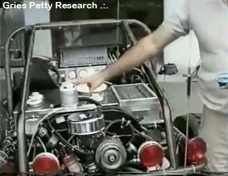
Stan Meyer Tour of Water Powered Dune Buggy from May 1992
Read Article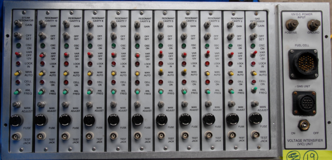
Mappings Between Meyer’s Hydrogen GMS Cards and Patent Schematics
Read Article
Excellent page. It looks new to me, I hadn’t seen it before! excellent information… I continue to finish my tests with the construction of the VIC.