Mappings Between Meyer’s Hydrogen GMS Cards and Patent Schematics
Stan Meyer’s Hydrogen Gas Management System (GMS) served as the central electronic control platform for his water fuel cell technology. While the patents describe the electrical circuits used in the system, the physical GMS rack reveals how those circuits were implemented as a coordinated set of modular control cards.
One particularly useful reference is the patent:
/content/images/2018/05/WO9207861.pdf
When studying the schematics in that patent alongside photographs of Meyer’s actual hardware, it becomes clear that many of the circuit blocks described in the patent correspond directly to the individual modules mounted in the GMS rack.
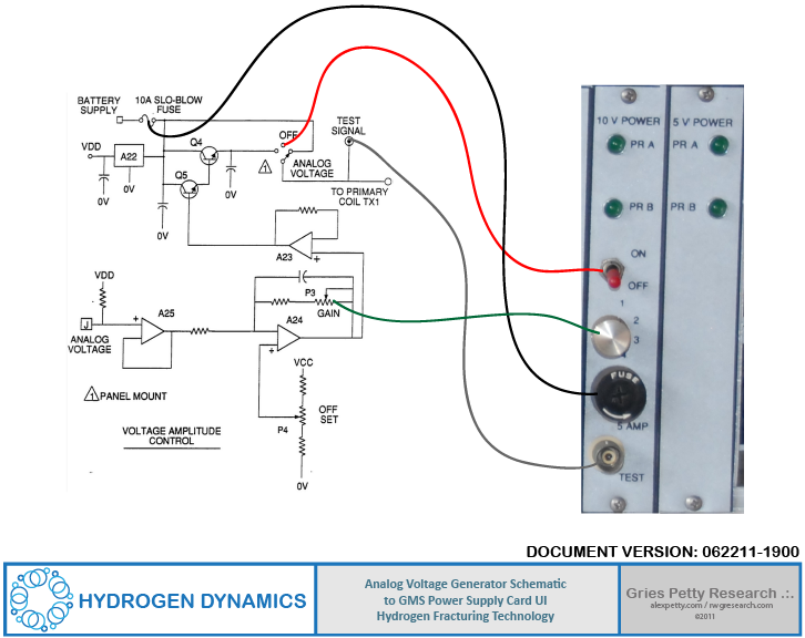
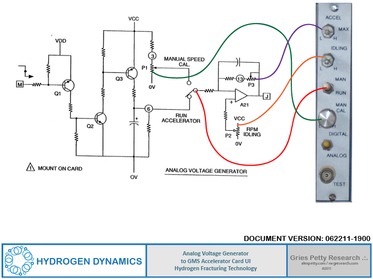
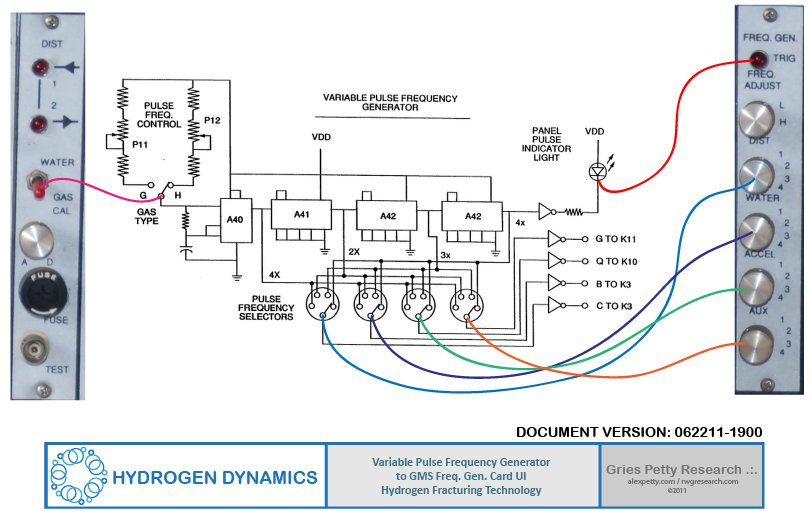
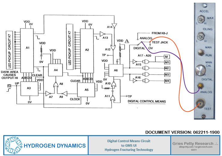
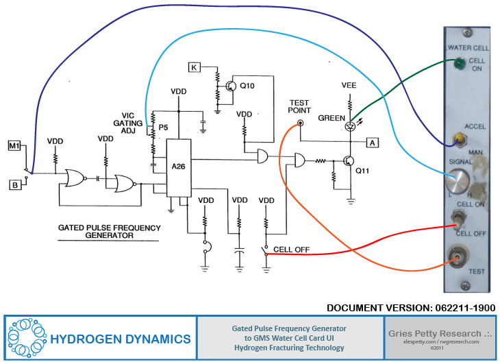
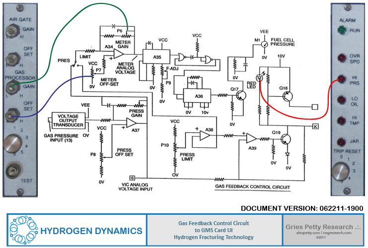
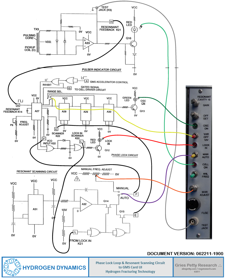
The diagrams below map those patent schematics to the user interface panels found on the GMS cards.
How the Hydrogen GMS System Works
The Hydrogen Gas Management System functions as the central controller for Meyer’s water fuel cell platform.
Although the patents describe many individual circuits, the GMS rack shows how those circuits were assembled into a coordinated control architecture.
At a high level, the system performs four major functions.
Signal Generation
The system generates the electrical signals used to drive the Voltage Intensifier Circuits (VIC). These include variable pulse frequencies, gated pulse trains, and voltage amplitude control signals that excite the water fuel cell assemblies.
Feedback and Control
Sensors and feedback circuits monitor the behavior of the gas generation process. These signals are fed back into the control electronics so the system can dynamically adjust operating conditions.
Gas Management
Once hydrogen and oxygen are produced, the GMS coordinates their routing through injectors and distributors so that the gases can be delivered to the engine in a controlled manner.
Safety and Operational Controls
Additional modules regulate system limits and vehicle operation. These include speed limiting, alarm monitoring, power regulation, and gate control for air and exhaust flow.
Viewed as a whole, the GMS rack functions much like the central nervous system of Meyer’s hydrogen technology.
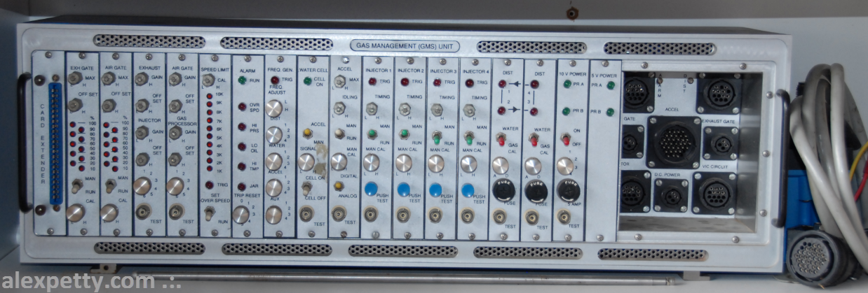
The Hydrogen GMS Rack
Below is the GMS rack with its card modules installed.

This unit was mounted in Meyer’s water-powered dune buggy.
For a complete tour of the dune buggy system see:

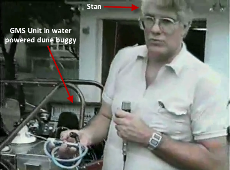
The GMS rack contains 18 module cards along with a cable connection interface used to connect the control system to the rest of the hydrogen fuel cell apparatus.
GMS Rack Card Modules
The modules below appear in the rack from left to right.
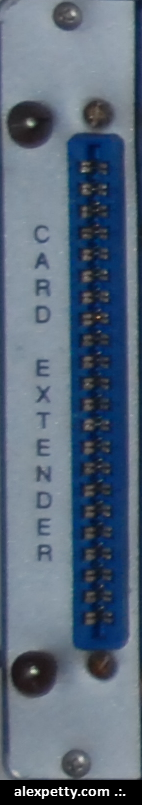
Card Extender Module
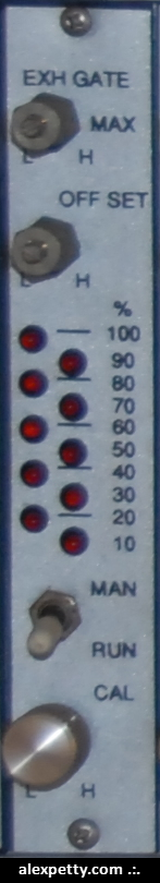
Exhaust Gate Module
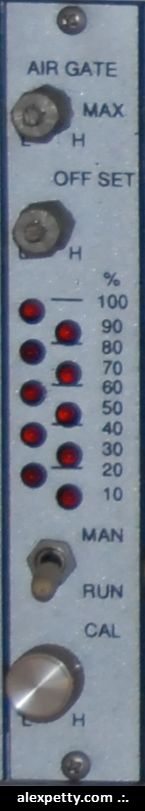
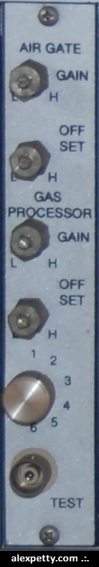
Air Gate Module
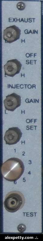
Exhaust Module
Air Gate 2 Module
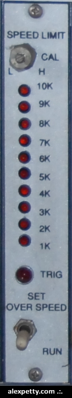
Speed Limit Module
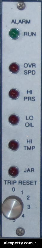
Alarm Module
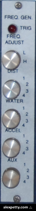
Frequency Generator Module
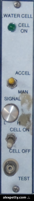
Water Cell Module
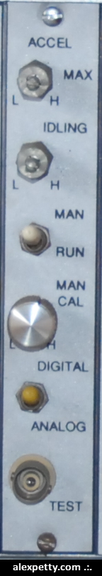
Accelerator Module
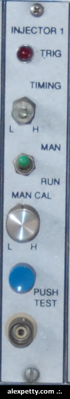
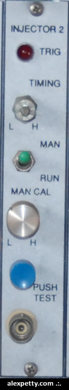
Injector 1 Module
Injector 2 Module
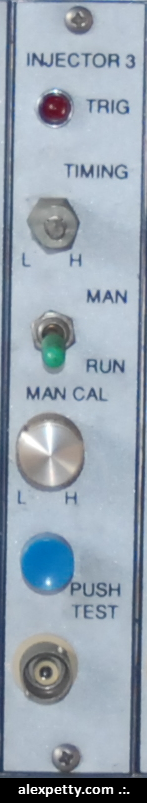
Injector 3 Module
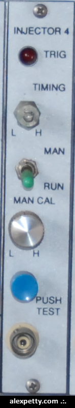
Injector 4 Module
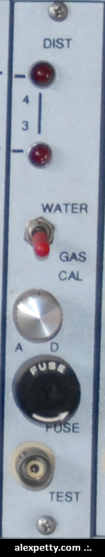
Distributor 1 Module
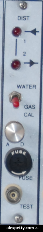
Distributor 2 Module
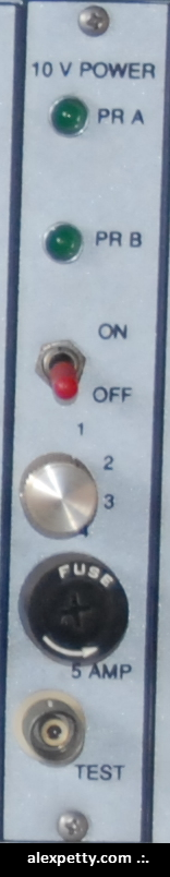
10V Power Module
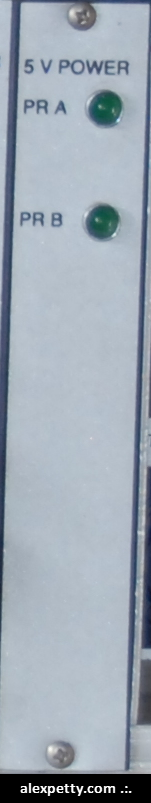
5V Power Module
Cable Connection Bay
The cable connection bay contains eight interface ports that link the GMS rack to the rest of the system.
- Alarm (7 pins)
- Dist (7 pins)
- Gate (2 pins)
- Accel (32 pins)
- Exhaust Gate (2 pins)
- TOR (8 pins)
- DC Power (2 pins)
- VIC Circuit (6 pins)
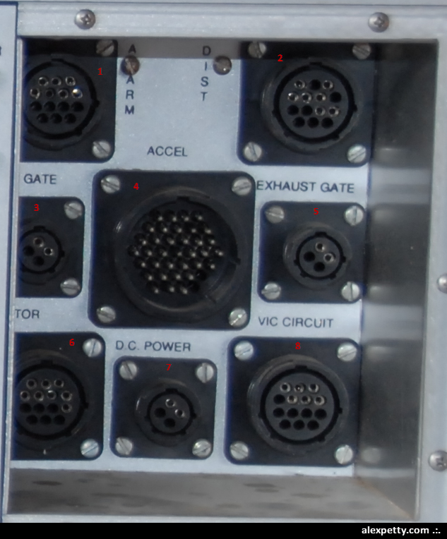
Through these ports the GMS unit connects to the Voltage Intensifier Array Unit.
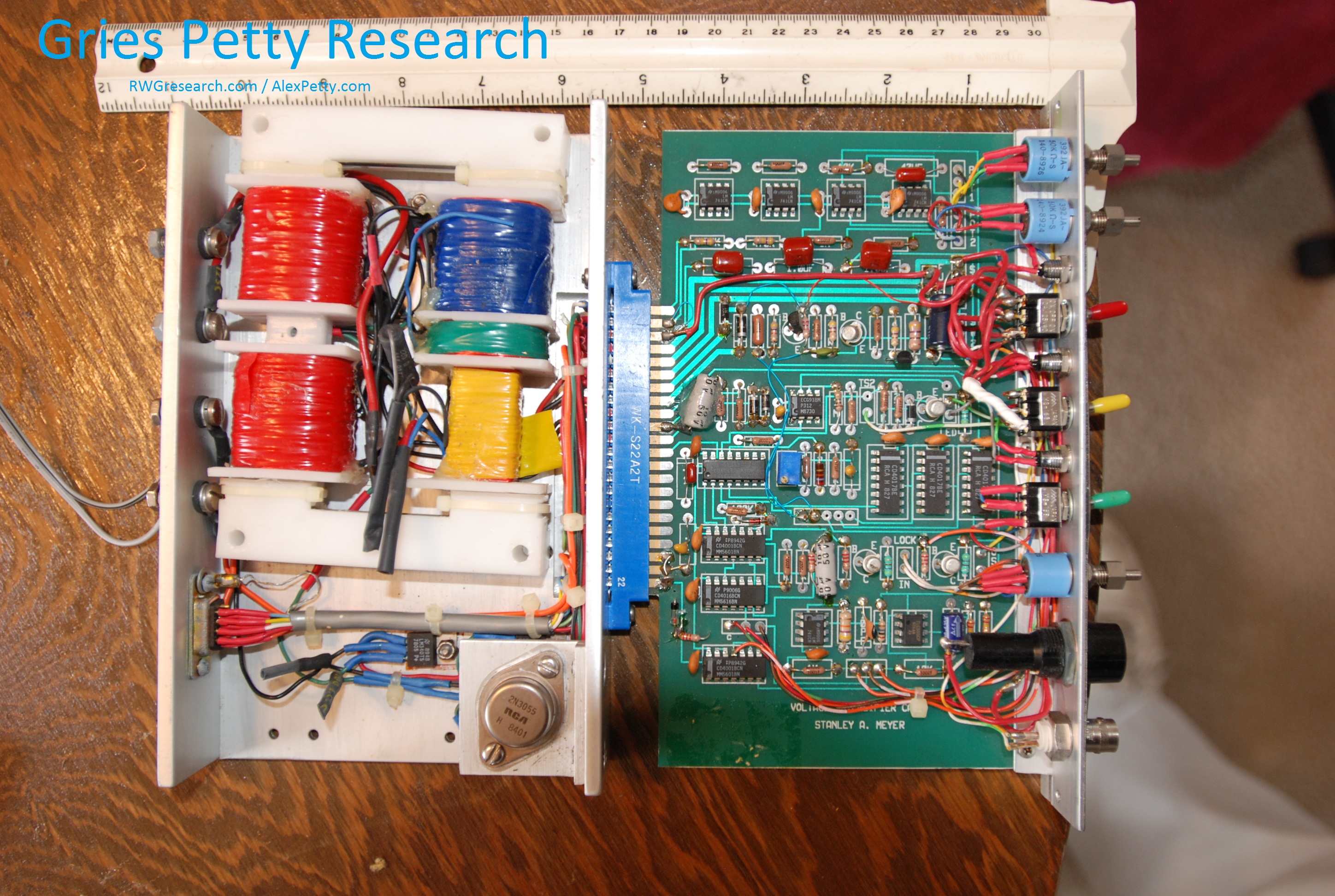
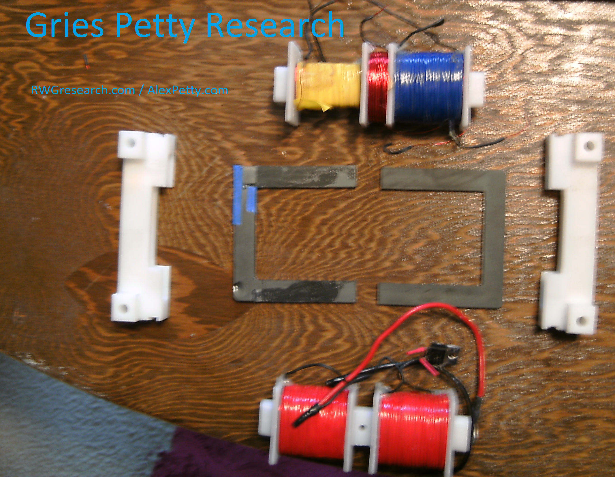
Voltage Intensifier Array Unit
This control rack was mounted at the rear of the dune buggy.
The rack contains:
- eleven module cards
- 12V DC terminals
- two cable interface ports
- a master power switch
The cards from left to right are:
- Steam Resonator
- Resonant Cavity 10
- Resonant Cavity 9
- Resonant Cavity 8
- Resonant Cavity 7
- Resonant Cavity 6
- Resonant Cavity 5
- Resonant Cavity 4
- Resonant Cavity 3
- Resonant Cavity 2
- Gas Processor
Each module provides the same user interface and controls its own dedicated Voltage Intensifier Circuit (VIC).
.:.