Meyer’s Gas Core Transformer

Could the very first patent Stan Meyer ever submitted hold an important clue to understanding his later water fuel inventions?
Meyer titled this patent “Electrical Particle Generator”, a name that would not immediately attract much attention. Interestingly, he never filed this patent in the United States. Instead, he submitted it only to the Canadian patent office, which at the time saw far less traffic.
One might wonder whether Meyer intentionally placed this invention into the public record while keeping its true significance somewhat hidden in plain sight.
The patent can be downloaded here:
/content/images/2018/05/SMeyer-CA1213671A1-Electrical_Particle_Generator.pdf
In his later patents Meyer referred to this device as the Unipolar Pulsing Core Transformer, a term that anyone familiar with his work will recognize.
But what exactly is this device?
Concept of Operation
The basic idea is illustrated below.
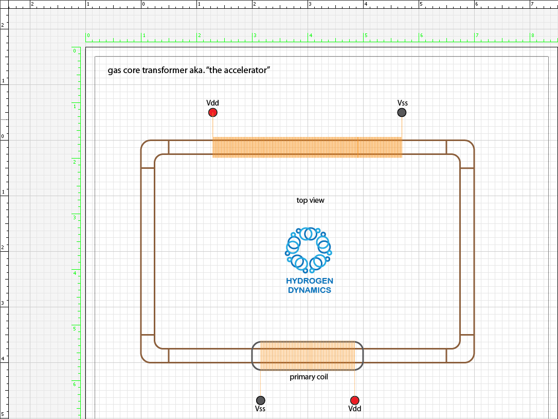
The concept involves circulating magnetized gas particles through a toroidal core structure while electromagnetic fields are applied through conventional transformer windings.
A natural question arises:
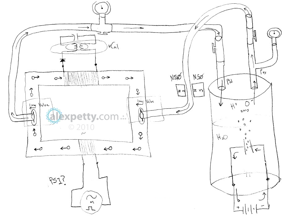
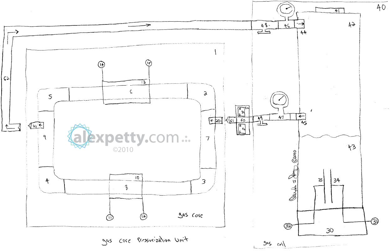
How can magnetized gas be introduced into the core?
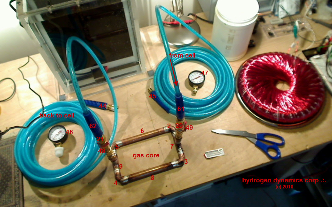
The following setup was the approach I used.
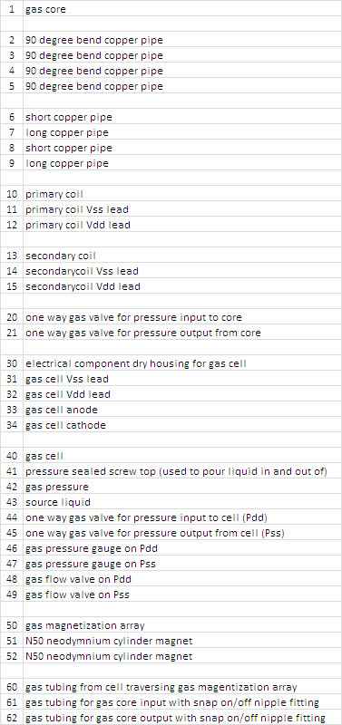
Below are photographs of my first physical implementation of the device.
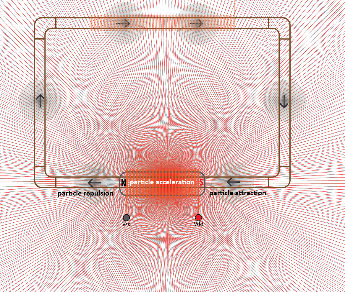
Magnetic Acceleration of Gas Particles
Once primary and secondary windings are placed on the core and the primary winding is energized, a magnetic field is produced.
If magnetized oxyhydrogen gas particles are circulating through the core, they respond to this magnetic field. The particles are attracted toward the south pole region of the field and repelled from the north pole region.
The result is an accelerating force acting on the gas particles.
As the velocity of the circulating gas increases, the particles move faster around the core loop. The faster the particles move, the greater the induced electromagnetic effect observed on the secondary windings as these small magnetic dipoles pass the coil.
In essence, the moving gas particles act like a stream of tiny magnets passing across the secondary winding.
Core Construction Materials
One practical note from experimentation concerns the material used to construct the fluid core.
PVC or flexible vinyl tubing works better than copper or aluminum tubing.
My first core, shown above, was built using copper tubing. In later builds I switched to PVC.
Copper and aluminum tend to dampen magnetic fields and therefore introduce losses that reduce the effectiveness of the system. Non-conductive tubing avoids this issue.
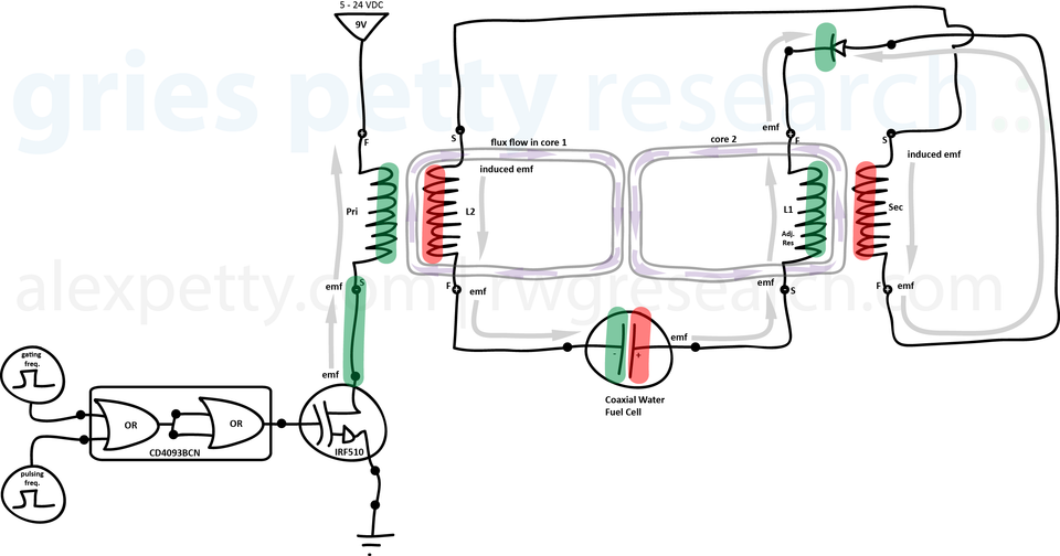
Meyer’s “Unipolar Magnetic Field Coupling”
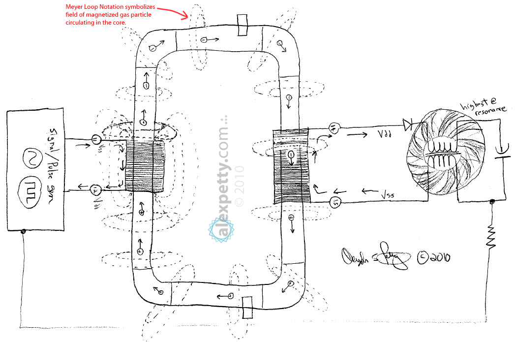
In many of Meyer’s later patents he refers to Unipolar Magnetic Field Coupling and uses a distinctive circular loop symbol in his diagrams.
An example of this notation is shown below.
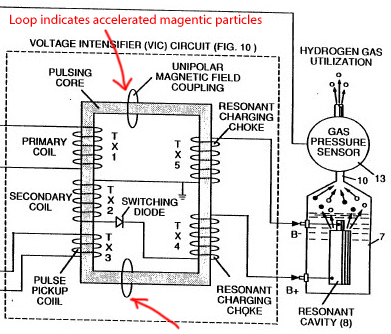
In these diagrams Meyer refers to the gas-filled pulsing core and its unipolar magnetic field interaction.
He consistently used these circular symbols in his block diagrams, but he never explicitly described their meaning.
My interpretation is that the circles represent the magnetic fields of magnetized gas ions circulating through the core. As these ions accelerate under the influence of the primary magnetic field, they pass across the secondary winding and induce electrical effects there.
This interpretation also appears consistent with the way Meyer referenced the pulsing core in several of his water fuel cell system diagrams.
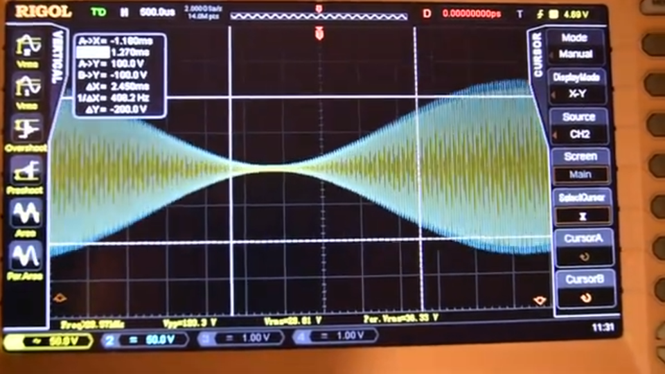
Experimental Results
It is worth mentioning that although this device is conceptually interesting, my own experiments with this type of transformer did not reveal any unusual energy effects.
In fact, these gas core transformers were generally less efficient than conventional solid ferrous core transformers.
So while the concept is intriguing and may help illuminate aspects of Meyer’s broader system architecture, it did not produce any extraordinary performance in my tests.
.:.