Operating Meyer's VIC
From studying the patents and technical writings of Stan Meyer, it becomes clear that the Voltage Intensifier Circuit (VIC) sits at the center of his water fuel cell system.
Meyer’s idea was straightforward in concept but unusual in execution. Instead of treating water electrolysis as a conventional current driven chemical process, he treated the water cell as a capacitor and attempted to manipulate the electric field inside the water using pulsed resonance techniques.
The basic structure is a set of stainless steel tubes arranged coaxially. Water fills the gap between the tubes and acts as the dielectric material.
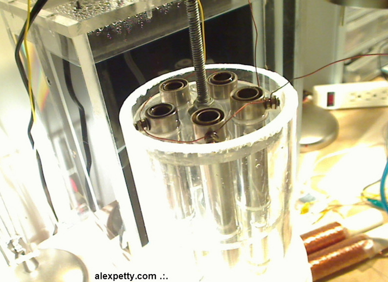
In electrical terms, this structure behaves like an asymmetric capacitor. Meyer referred to this device as the Water Fuel Cell (WFC) or simply the water capacitor.
The Voltage Intensifier Circuit is the network of coils, diodes, and switching electronics used to drive this capacitor in a specific pulsed mode.
Resonant Pulse Operation
The VIC operates by driving the water capacitor with a sequence of square wave pulses. When the circuit is tuned correctly, these pulses interact with the inductors in the system to create resonant oscillations.
The inductors surrounding the capacitor form an LC network with the water capacitor. Energy introduced by the pulse waveform circulates through this network, producing large voltage potentials across the capacitor plates.
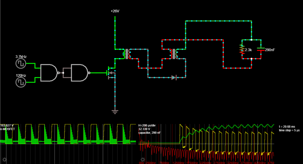
For reference, I built a partial simulation of the VIC using the Falstad circuit simulator.
The important point is that the VIC attempts to build voltage across the water dielectric while limiting current flow through it.
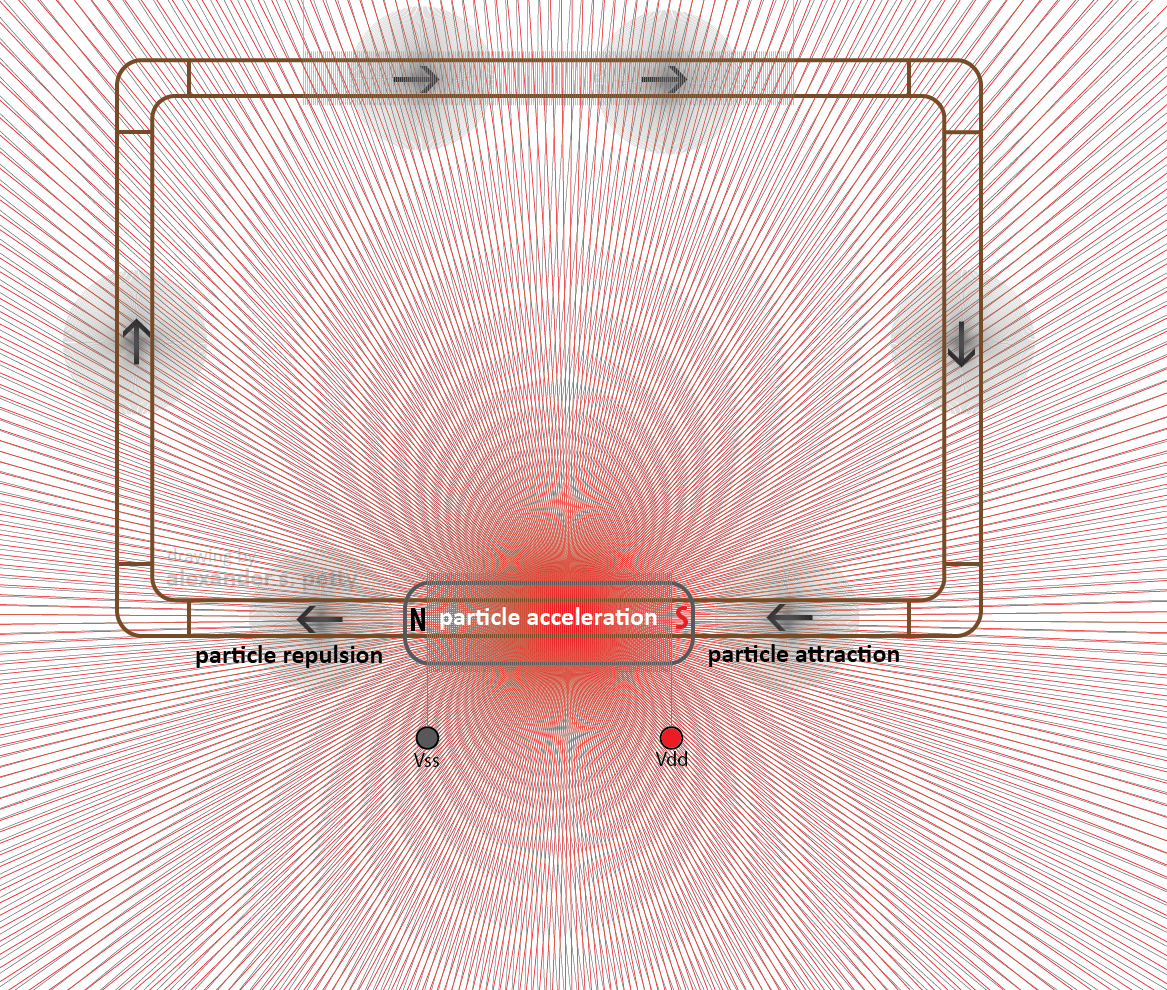
Electric Field Effects in the Water
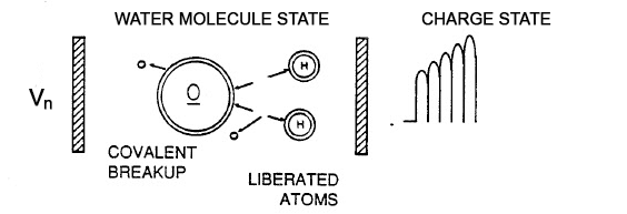
Meyer proposed that very high electric field strength across the water capacitor would polarize the water molecules between the plates.
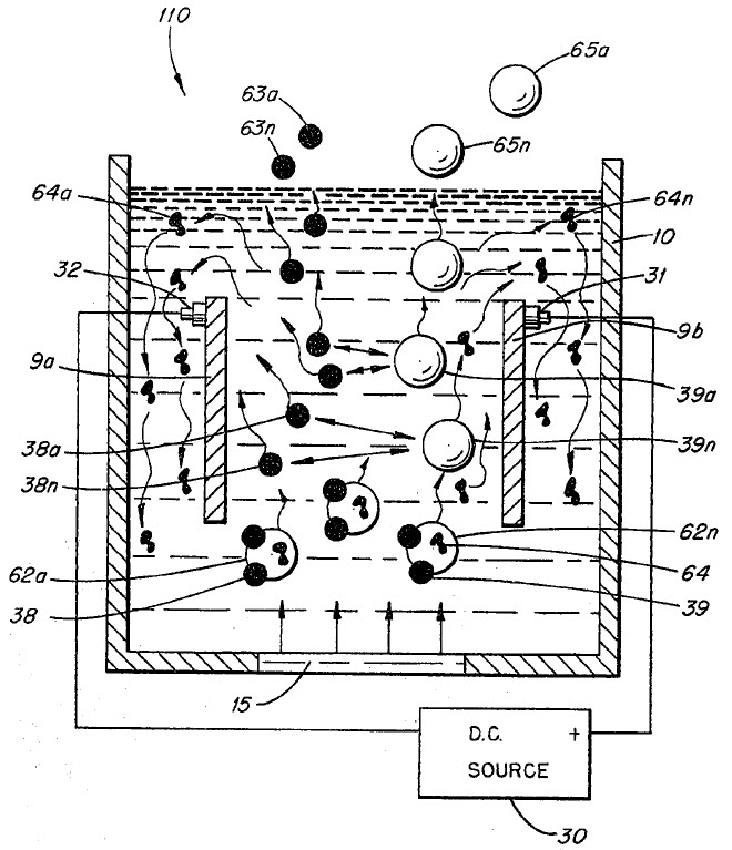
Water molecules are dipolar. Oxygen carries a partial negative charge while hydrogen atoms carry partial positive charge.
When a strong electric field is applied across the water capacitor, the molecules tend to orient themselves along the field lines. As the electric field increases, the orientation becomes stronger.
Meyer suggested that under sufficiently strong electrostatic stress, the molecular bonds between hydrogen and oxygen could be destabilized.
The Key Operating Principle of the VIC
The most important design feature of the Voltage Intensifier Circuit is that the water capacitor is not allowed to discharge between pulses.
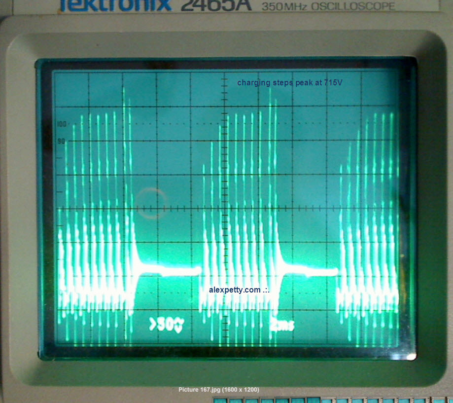
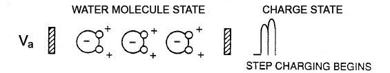
Instead of charging and discharging like a normal capacitor in a pulsed circuit, the VIC attempts to step charge the capacitor so that each pulse begins at a slightly higher voltage than the previous one.
In effect, the voltage across the capacitor rises in discrete increments.
Research Work
My research partner Russ Gries and I have spent a number of years studying and experimenting with Meyer’s VIC architecture.
What follows is an illustrated sequence describing our current working interpretation of the circuit’s operation.
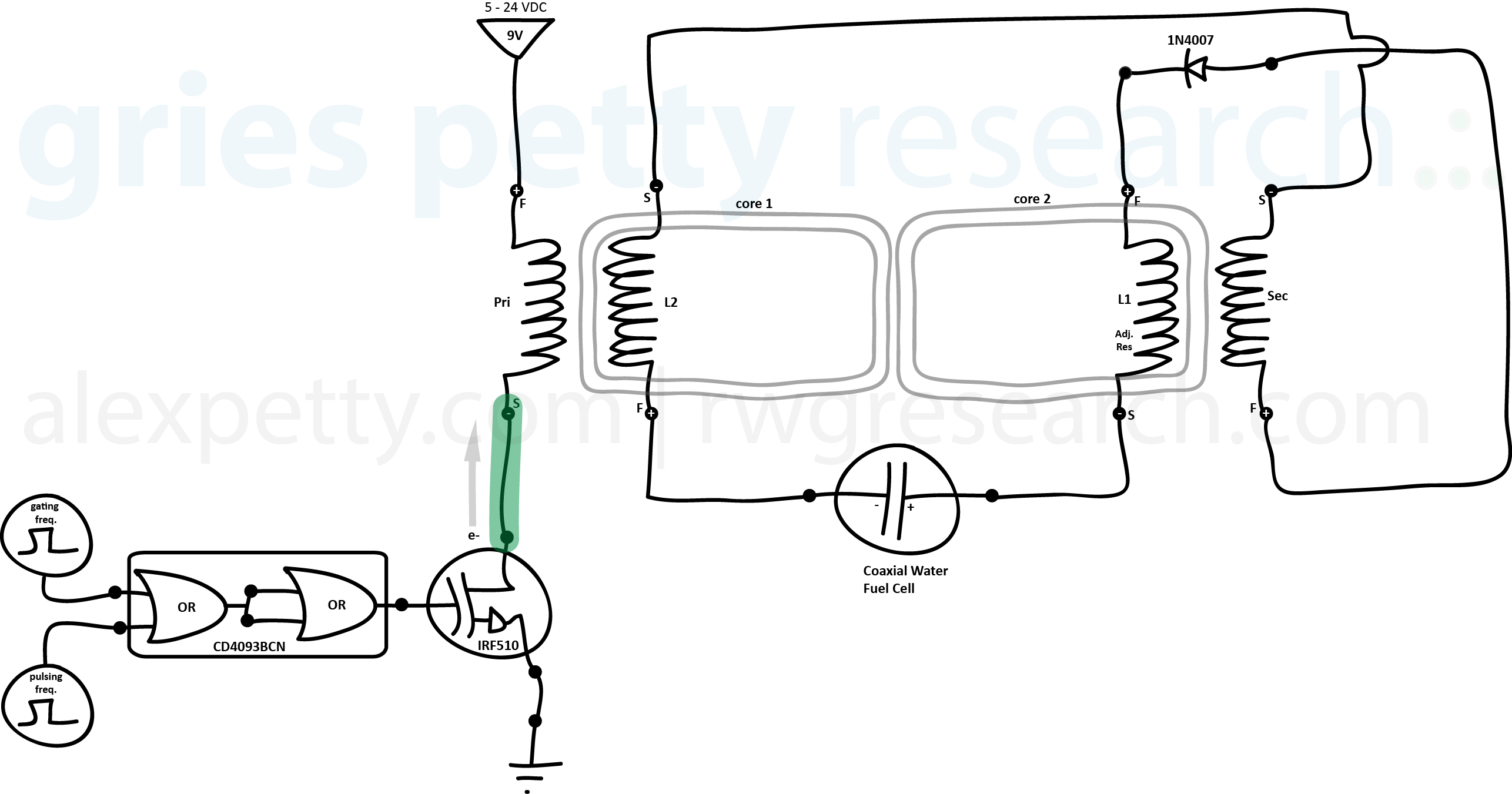
VIC Circuit Structure
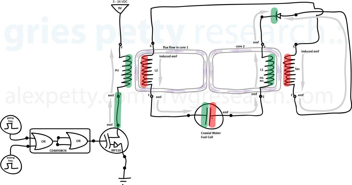
The circuit diagram included in Meyer’s patents typically appears in the following form.
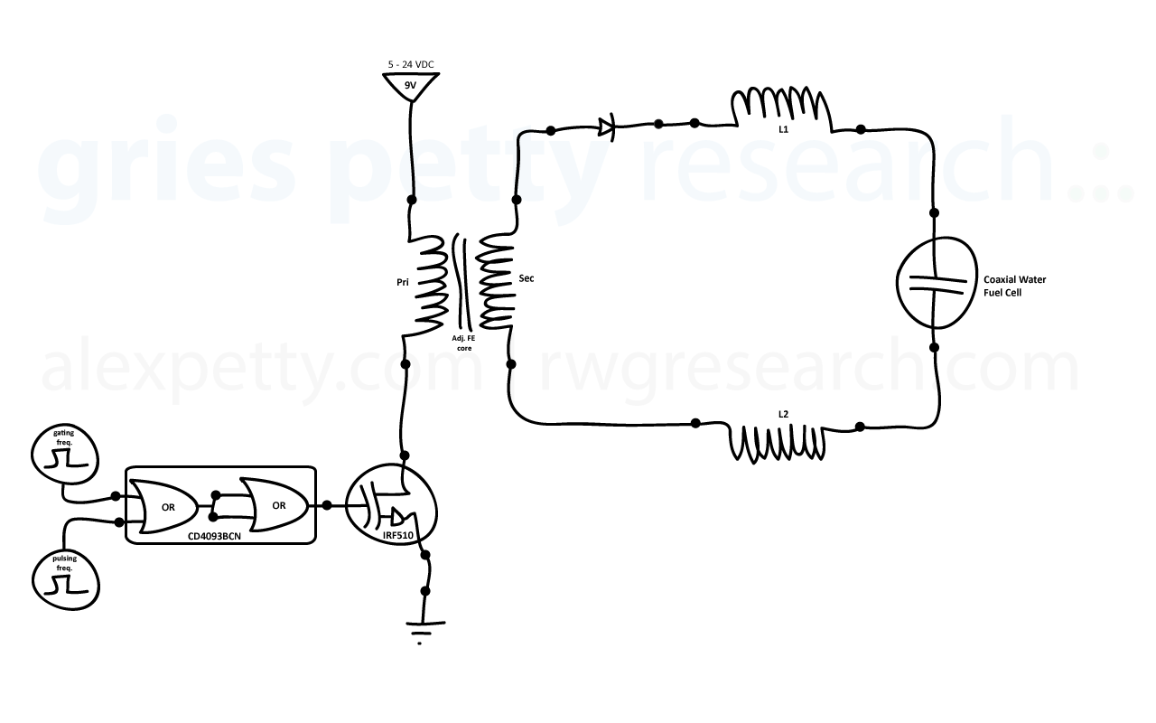
However, after analyzing the current paths and magnetic coupling relationships, we find that the circuit can be represented more clearly in the following form.
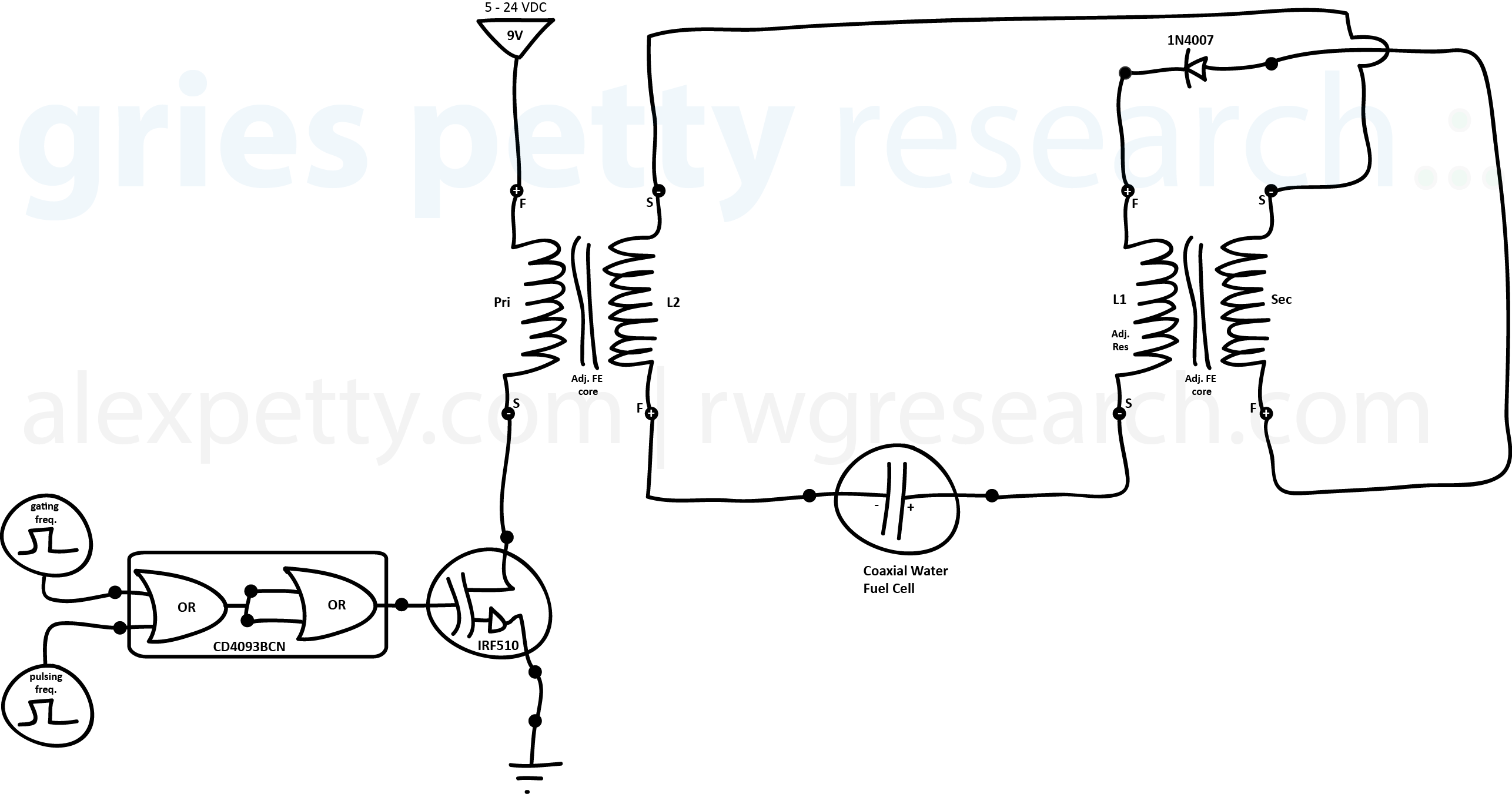
This equivalent drawing makes the interactions between the coils and the water capacitor easier to visualize.
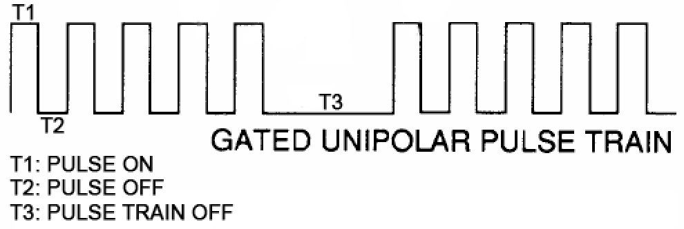
Pulse Timing
Three timing intervals are used when discussing the circuit.
T1
Pulse applied to the primary coil of the transformer.
T2
Pulse removed and magnetic fields collapse.
T3
Gated off time between pulse sequences.
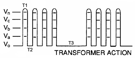
Step Charging the Water Capacitor
During T1, the primary coil of the transformer is energized. Magnetic coupling induces current in the secondary coil L2, which drives charge into the water capacitor.
Because the circuit is designed to inhibit discharge during T2, the charge stored in the capacitor accumulates from pulse to pulse.
Meyer described these increasing voltage levels as:
Vo → Va → Vb → Vc → Vn
Back EMF Contribution
When the pulse ends, the magnetic fields stored in the inductors collapse.
This collapse produces back electromotive force (BEMF) pulses that also feed energy back into the capacitor.
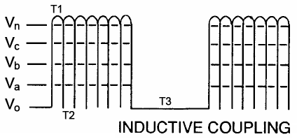
The result is that the capacitor experiences additional voltage impulses even during the off phase.
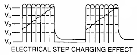
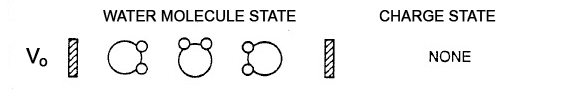
Molecular Response Stages
As the voltage across the water capacitor increases, the electric field inside the dielectric becomes stronger.
Vo
Initial condition.
No voltage applied.
Va
Molecular polarization begins.
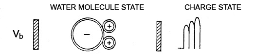
Vb
Molecules become strongly aligned with the electric field.
Vc
Electrical stress on molecular bonds increases.
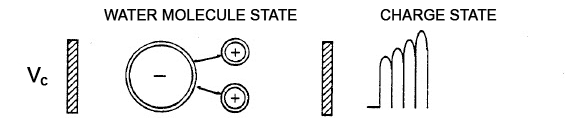
Vn
Meyer proposed that molecular separation occurs at this stage.
Pulse Sequence Example
Step 1
MOSFET gate receives the drive waveform.
Step 2
Current flows through the primary winding, generating a magnetic field.
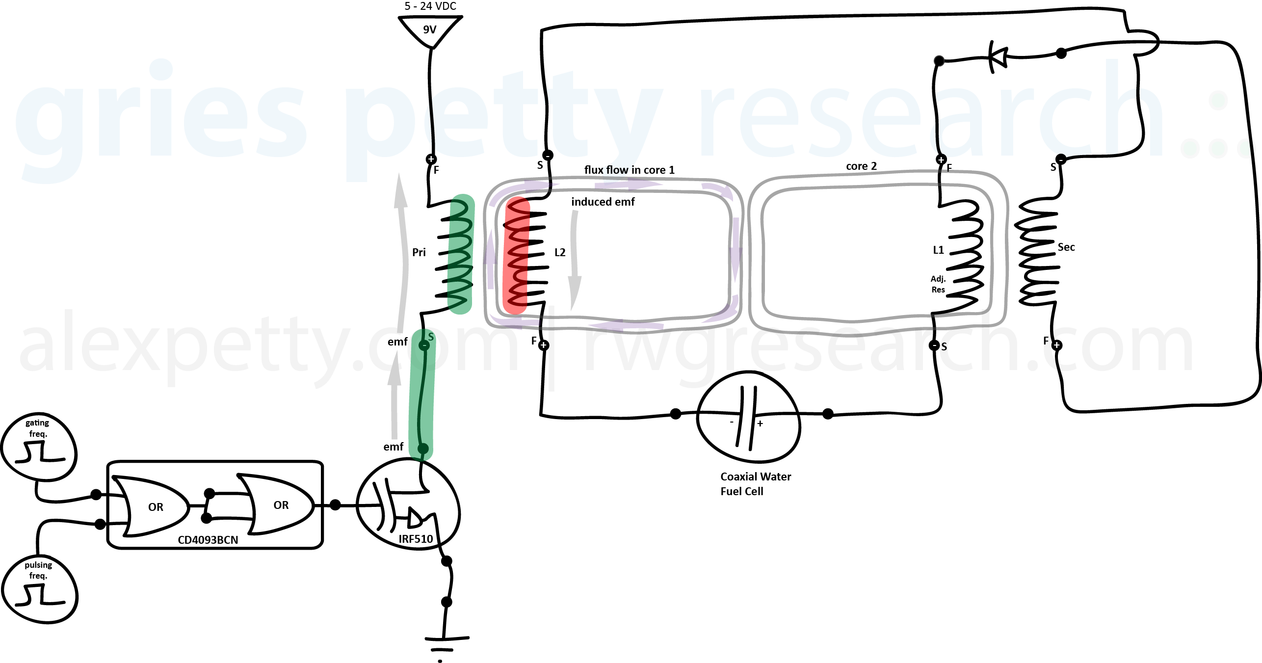
Step 3
The magnetic field induces current in L2 which charges the water capacitor.
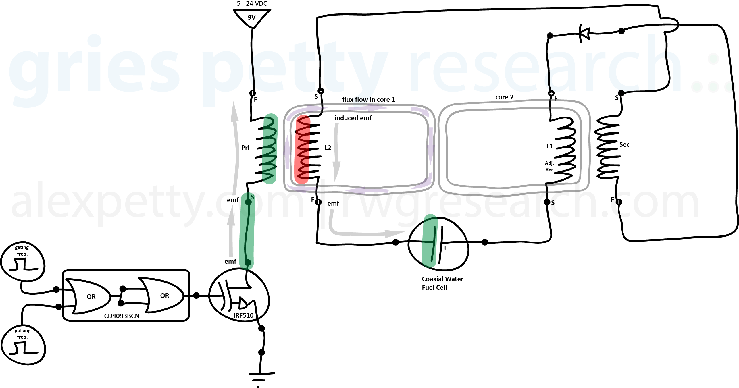
Step 4
Displacement current flows toward L1 and energizes the coil.
Step 5
The diode blocks the forward current path.

Step 6
Magnetic field collapse produces BEMF pulses.
Impedance Matching
Proper operation requires the impedance of the circuit elements to be matched.
Where:
- R1 represents the resistive characteristics of the secondary coil.
- Z2 represents the impedance of coil L1.
- Z3 represents the impedance of coil L2.
- RE represents the electrical resistance of the water dielectric.
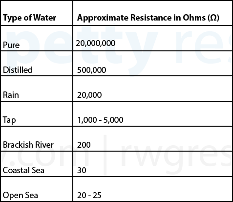
The resistivity of the water depends strongly on contamination levels.
Electron Bounce Phenomenon
Meyer described an additional effect he called the Electron Bounce Phenomenon.
In this mode, the magnetic coupling between the coils becomes strong enough that electrons within the copper conductors are influenced by the magnetic flux field.
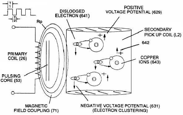
According to Meyer’s description, this effect alters current flow within the circuit and further limits discharge of the capacitor during pulse transitions.
This effect remains an area of ongoing investigation.
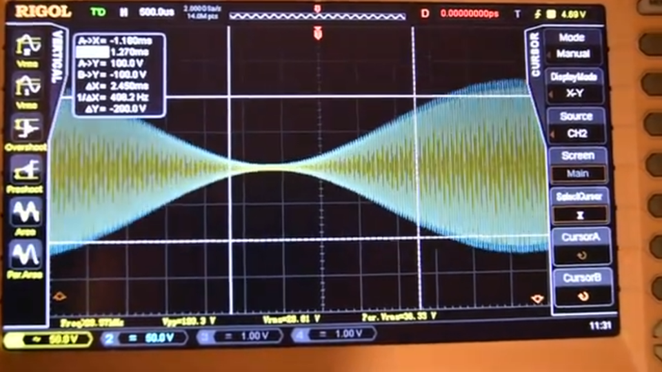
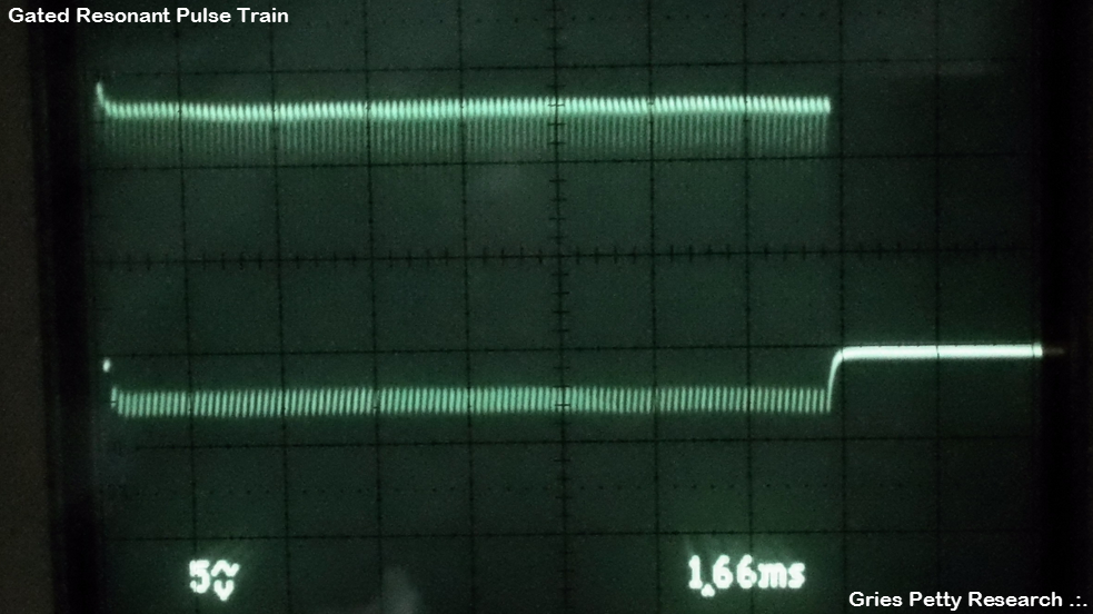
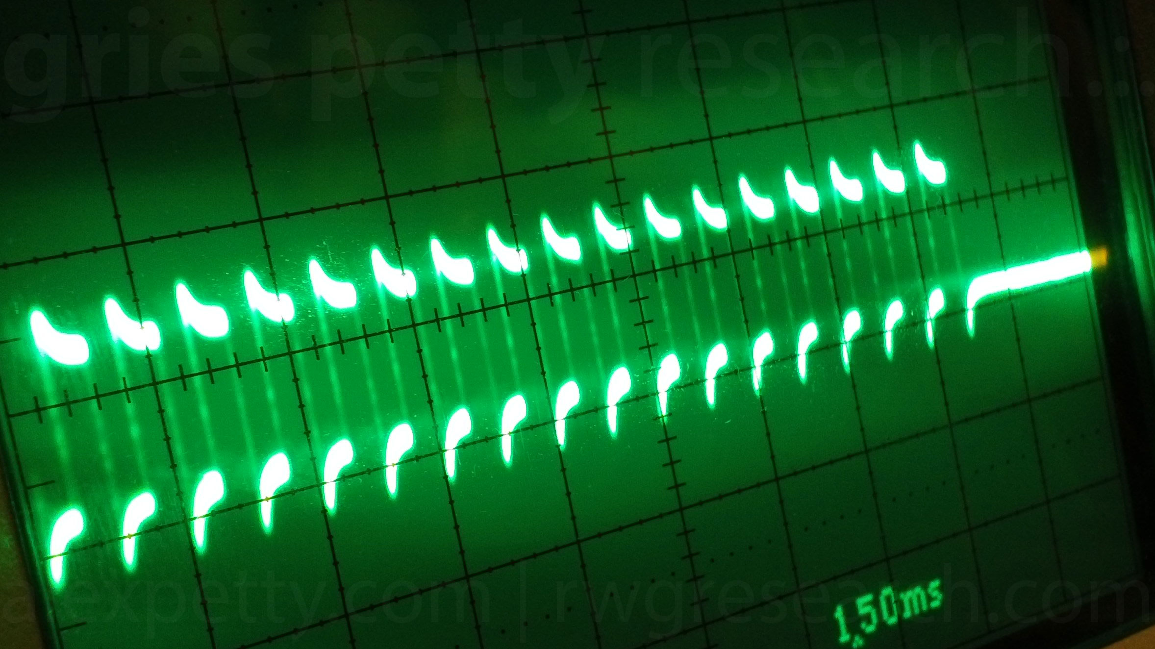
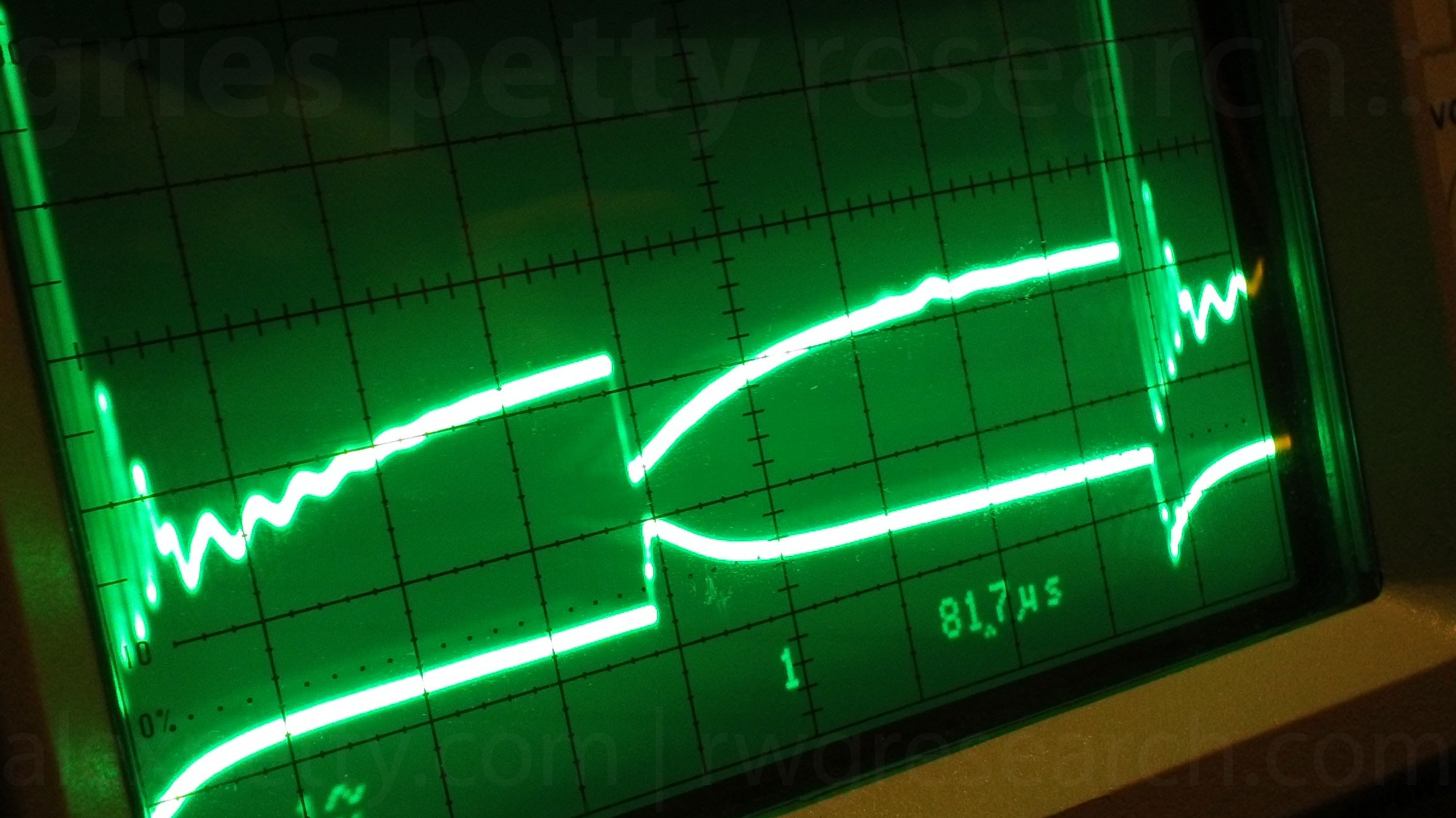
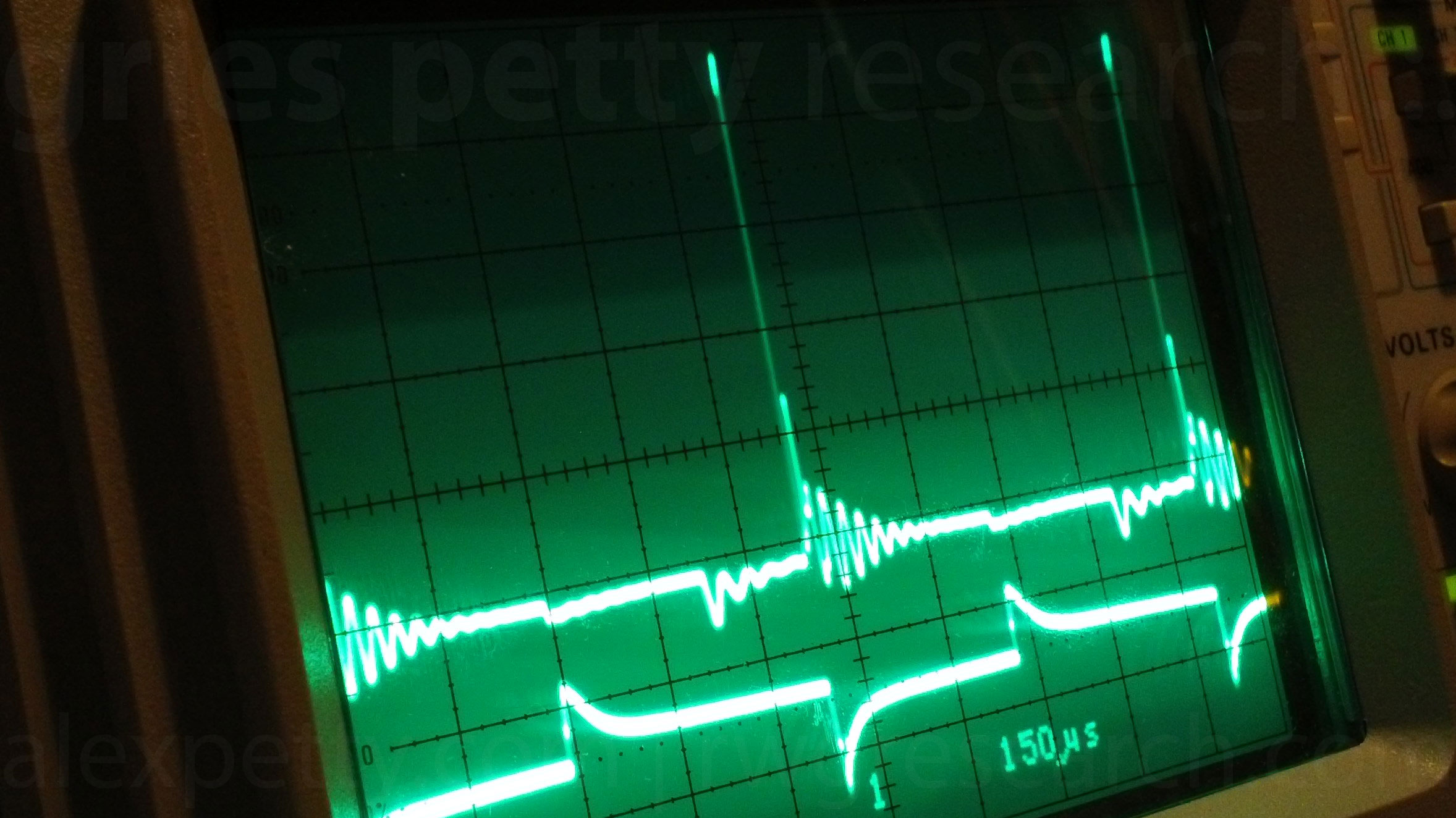
Oscilloscope Measurements
MOSFET Gate Signal
Primary Coil Behavior
L2 and Capacitor Response
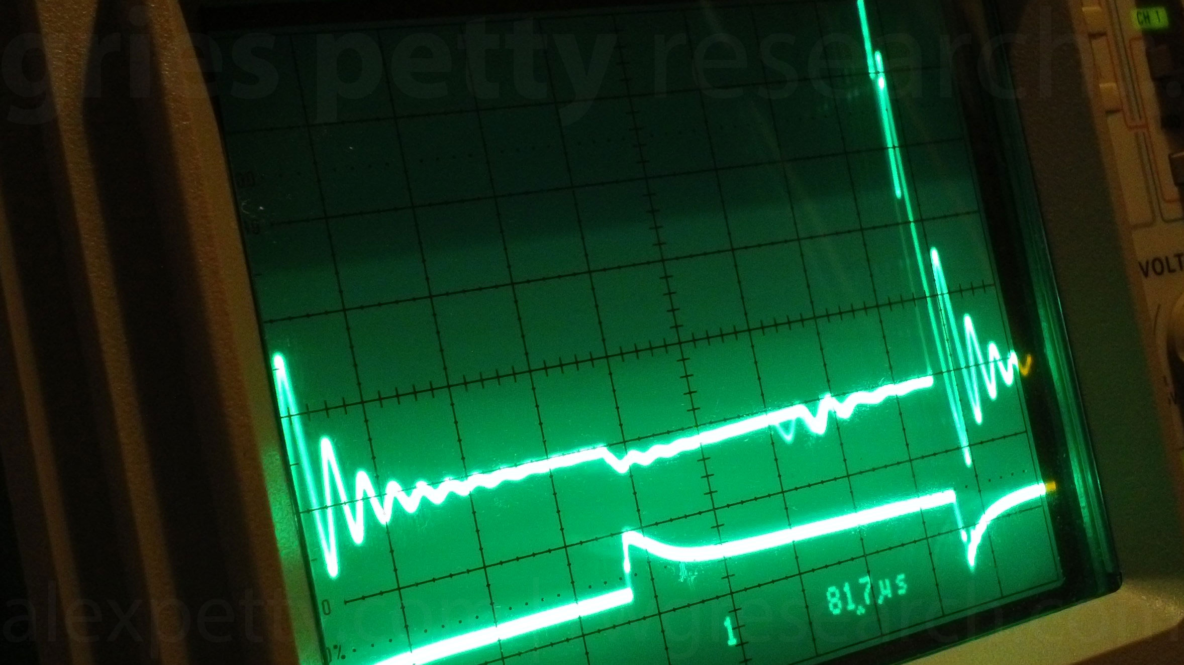
Capacitor Anode
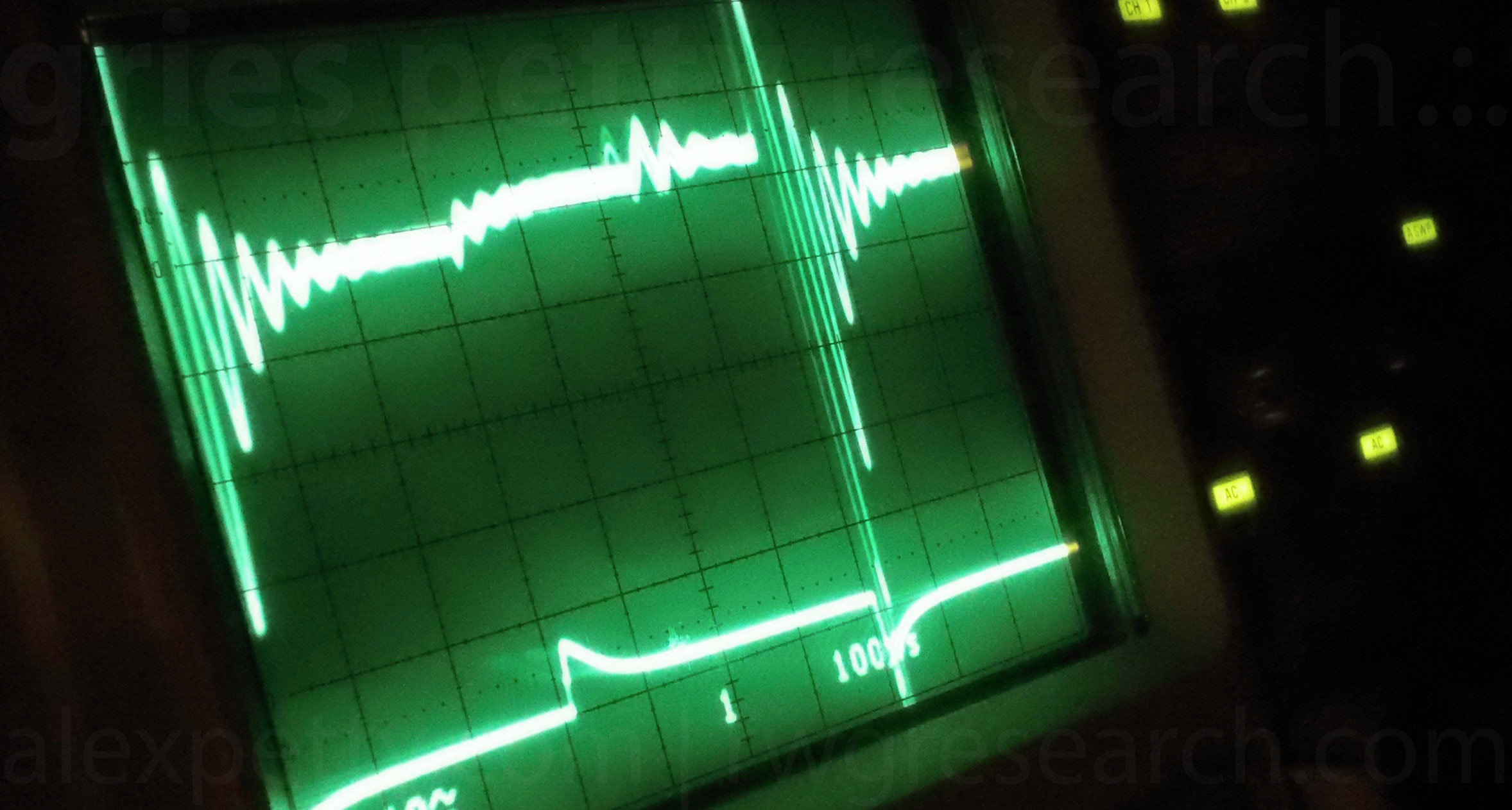
L1 Diode Junction
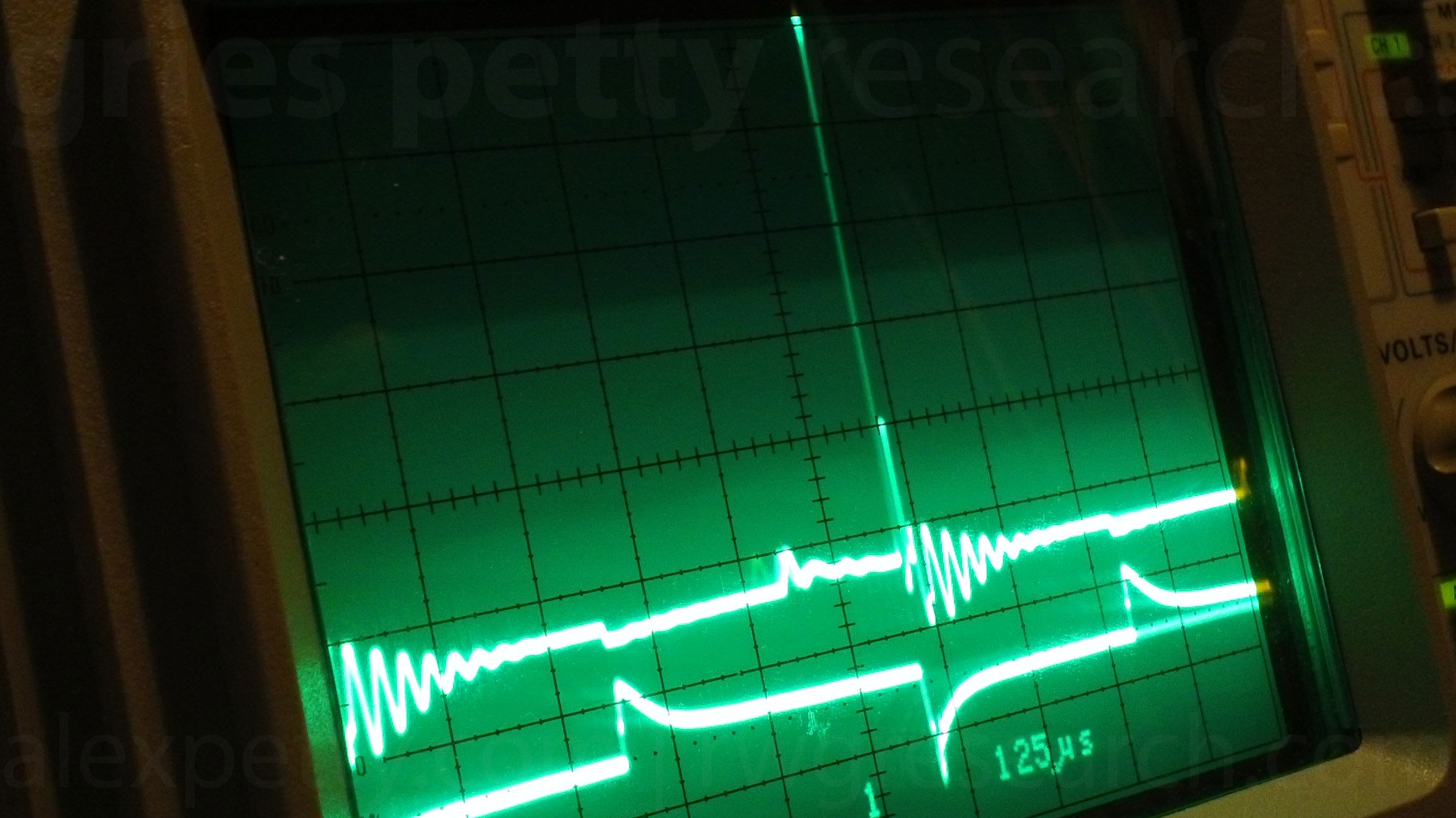
Secondary Coil
Ongoing Work
We are continuing to investigate the charge and magnetic flux paths within the VIC, particularly during the pulse transitions and during the regime Meyer referred to as electron bounce.
Further measurements and analysis will be posted as the research progresses.
Alex .:. & ~Russ
Participate in the Research
Forum discussion
http://open-source-energy.org/?topic=2118.msg28654
Email group
https://groups.yahoo.com/neo/groups/meyer_wfc_replication/info
Acknowledgements
Stanley A. Meyer
Quantum Gravity Research
Applied Harmonics
GPSsonar
Ravenous Emu
Don Gable
The Open Source Research Community
Footnotes
- Meyer frequently referred to the dielectric constant of water using units of resistance. In physics, the dielectric constant is a dimensionless value describing the ratio of a material's permittivity relative to vacuum. For water at 25°C this value is approximately 78.54.
Authors
Alex Petty
Russ Gries