Simple WFC Energization Circuit
In response to those of you who want to build a water fuel cell but feel that you may not have enough experience in electronics to get started, I am presenting here the simplest analog circuit I have designed for the purpose of pulsing water fuel cells.
The goal of this circuit is to allow you to excite your cell in a resonant condition, which is the operating state that Meyer repeatedly referred to in his patents and technical papers.
To tune your circuit into resonance, you will primarily adjust capacitor C2.
The resonant frequency for the system can be estimated using the equation below.
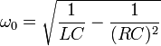
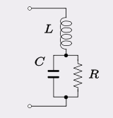
The circuit model corresponding to this equation is shown here.
To use the equation you will need to know three things:
- the inductance of L1
- the capacitance of C5
- the resistance presented by the water between the plates of C5
Once you have calculated the approximate resonant frequency, you can select a capacitor value for C2 that produces square wave pulses at that frequency.
If you are unsure how to calculate the exact value, simply tune the circuit experimentally. Use an oscilloscope and adjust the value of C2 while watching the pulse amplitudes. When the circuit approaches resonance the pulse amplitudes will noticeably increase.
If you do not already have an oscilloscope, get one. It is an indispensable tool for this type of work.
Gate Timing
Once the resonant frequency has been dialed in, capacitor C3 can be added to introduce a gating interval.
The gate provides an off-time in the pulse train.
This off-time allows the water capacitor to partially discharge so that the step-charging process can repeat again on the next cycle. The gating interval also allows soliton-like pressure structures to form between the plates of the water capacitor.
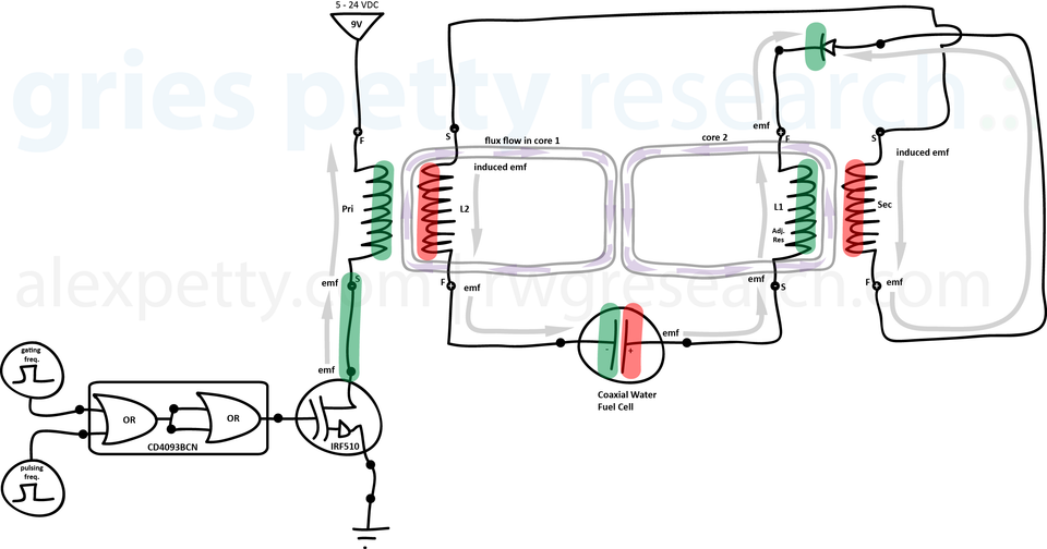
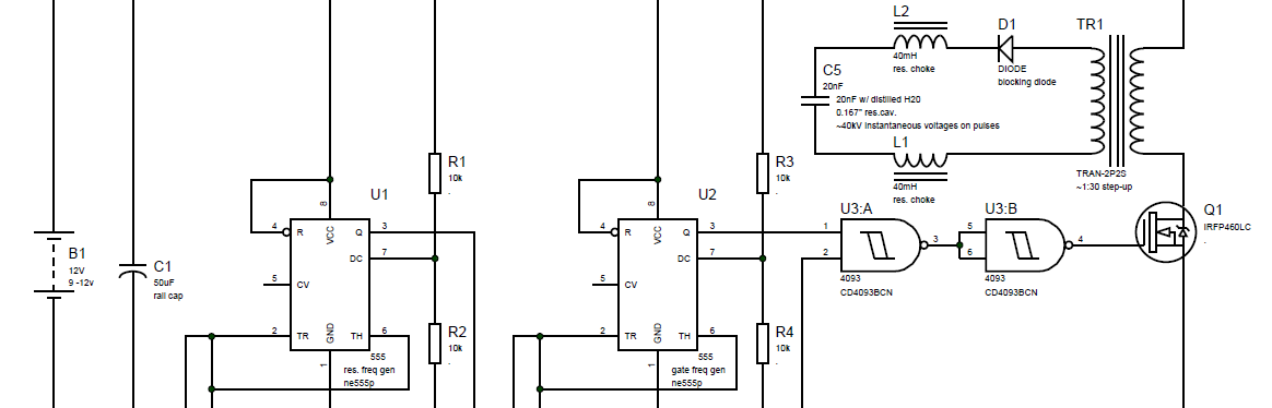
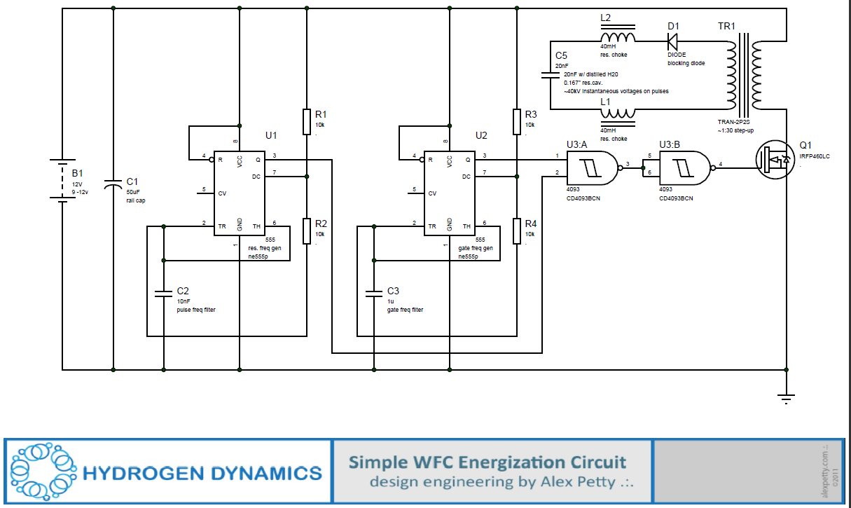
Energization Circuit
The full circuit is shown below.
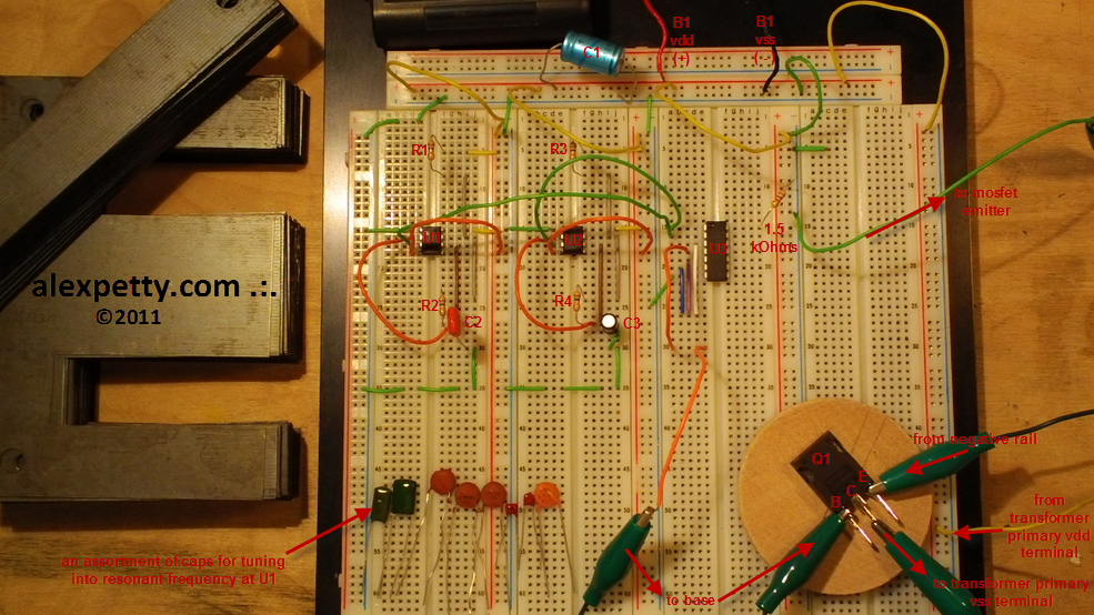
Breadboard Implementation
Below is a photo of the circuit implemented on a breadboard. This is included to help those who may find it easier to translate a schematic into physical wiring when a real example is visible.
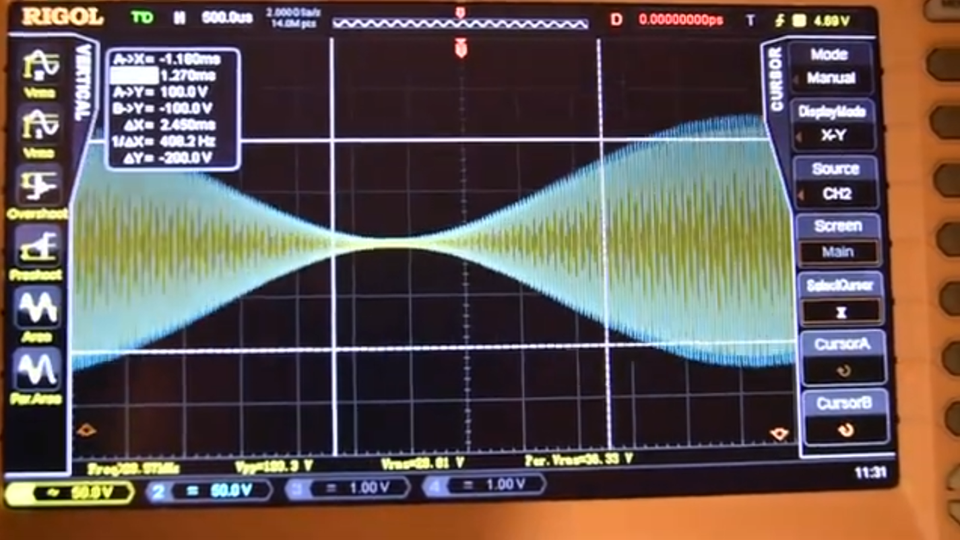
Oscilloscope Views
The waveform observed at different points in the circuit should resemble the following.
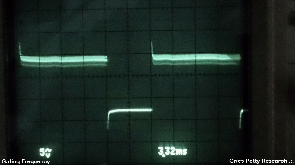
Gate Frequency
Measured at breadboard column 3 (third column from the left), pin D15 on U3.
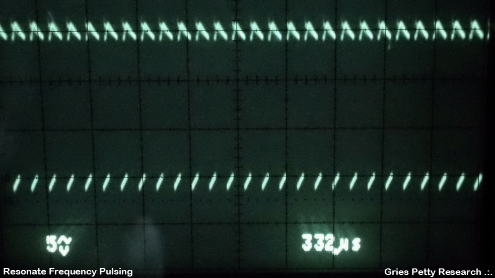
Resonant Frequency
Measured at breadboard column 3, pin D16 on U3.
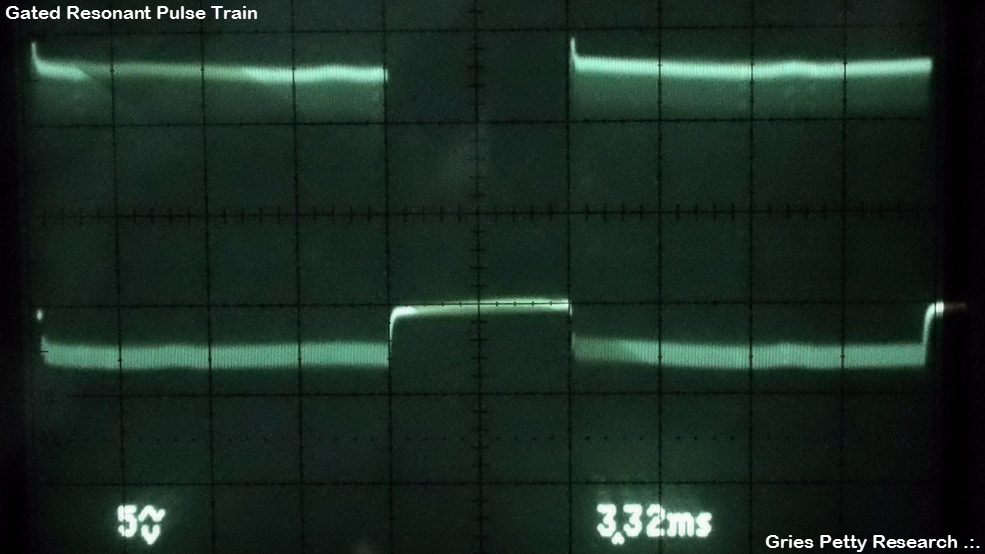
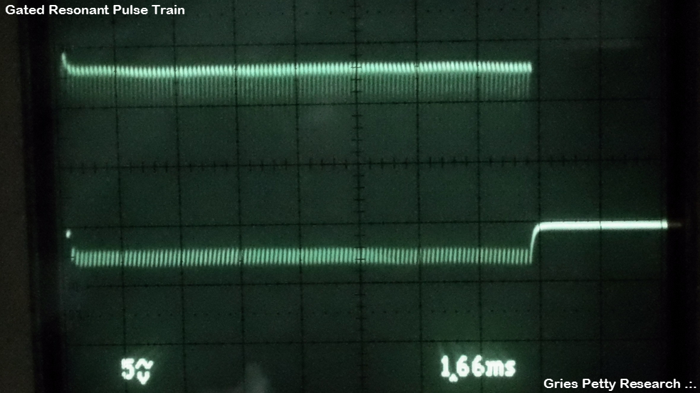
Gated Resonant Pulse Train
Measured at breadboard column 3, pin D30.
Higher Time Resolution View
Expected Voltage Behavior
If the Voltage Intensifier Circuit (VIC) hardware is well constructed and the energization circuit is properly tuned to the hardware, the waveform that appears between L2 and C5 can reach extremely high instantaneous voltages.
Values exceeding 40 kV are not uncommon under properly tuned resonant conditions.
These very high electric field strengths are what facilitate the electrical polarization process that Meyer described.
Important Note About Cell Parameters
A question that is often asked is:
“What is the capacitance of a Meyer cell?”
The truth is that the exact component values are less important than achieving resonance.
Your real goal is to cause the water cell to pulse at the resonant condition where
capacitive reactance of C5 = inductive reactance of L1 (and L2).
This resonant frequency is determined by:
- the inductance of the coils
- the capacitance of the water cell
- the resistance of the water dielectric
Once these parameters align, the system naturally enters the resonant condition.
Sharing the Design
Please feel free to share this circuit design and use it however you wish. I am placing it into the public domain.
If you re-post it, I would appreciate attribution and a link back to my blog.
I hope you find it helpful.
.:.