Stan Meyer Water as Fuel Lecture in Denver on May 1997
I am writing today about the “Water as Fuel” lecture presented by Stanley Meyer at the Denver Marriott in May of 1997.
The video below contains a detailed presentation in which Meyer explains the principles behind his water fuel cell technology and the electrical polarization process he claimed could be used to:
- power cars, trucks, trains, boats, ships, and aircraft
- operate industrial equipment
- generate electrical power
- and even provide propulsion for space exploration
In the lecture Meyer outlines several technologies he said he had developed:
- A method for efficiently producing hydrogen gas from water.
- A system for slowing hydrogen’s burn rate by mixing controlled amounts of non-combustible gases with the hydrogen before ignition.
- A process for increasing the energy yield of the water molecule by extracting electrons and electrically stressing the atom to sub-critical states prior to combustion.
- A retrofit system allowing existing engines to operate on water fuel without extensive modification.
- A method of tapping what Meyer described as a “limitless supply of electrical energy” from the water molecule itself.
Meyer also stated in the lecture that most of the manufacturing challenges preventing mass production of retrofit kits had already been resolved.
The full lecture video is presented below.
Transcript
(00:55)
Thank you very much and thank you for coming this morning.
I am not an early riser so if I am not activated you can kick me a little bit and we’ll go on.
Communication is really the name of the game in trying to develop new technology and get it commercialized.
We do release a publication we call The Birth of New Technology. On the TSR’s that you have received it contains a brief overview of the technology base. The complete manual is about 230 pages and provides a detailed explanation of how and why water can be used as fuel.
(Note: Stan Meyer passed away on March 21, 1998. The document he references is no longer available through his organization but can now be found online.)
(01:50)
I have a very short period of time. It is difficult to condense four hours of presentation down to less than one hour, so please bear with me.
I will be presenting the material at a fairly high technical level. After the presentation feel free to ask questions.
(To the A/V team)
Can you turn on the slide projector?
Figure 1

(02:21)
During the Arab oil embargo I conducted an analysis to understand why we had an energy crisis.
I realized that a relatively small country in the Middle East had the ability to cripple the United States because the industrial base of the entire world depends on one thing:
the supply and utilization of energy.
My background is fairly diversified. I have worked in high-technology research and development, product engineering, and corporate entrepreneurship. I have also developed many products independently.
When the embargo struck the United States I owned a very successful truck parts business. But when the trucks stopped moving and the supply chains began to fail I began asking an important question:
How long could the food supply chain continue before the country ran out of supplies?
I was told that if the trucks did not start moving again within 27 days, the national food distribution system would collapse.
(03:23)
When I studied the problem I realized that the solution would not come from governments or multinational corporations.
Historically most technological breakthroughs come from individuals or small groups who recognize a problem and decide to solve it.
So I went into my laboratory and prayed.
I said:
“God, I love my country. It is the greatest country in the world. If you help me provide a power supply for this country, I will do whatever you ask of me.”
After that experience I felt compelled to pursue this technology.
Figure 2 – Meyer Patents


(04:04)
The challenge was enormous.
From my experience in high-technology development I understood the many ways that breakthrough technologies can be suppressed or blocked.
So the first objective was to legalize the technology through the patent system.
There are many loopholes in patent law that must be understood in order to protect new inventions from being blocked.
It became obvious that solving the energy problem would not come from a single “miracle patent”. It would require multiple patents working together as a complete system.
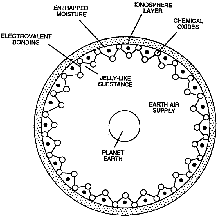
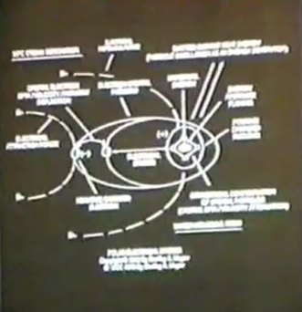
Figure 3 – “Spaceship Earth”
(05:40)
For nearly seventy years we have powered internal combustion engines with fossil fuels.
The chemical oxides produced by combustion are released into the atmosphere. These oxides combine with the ionosphere and reduce the amount of sunlight reaching the Earth.
I visited Scandinavia and saw forests dying because sunlight was being reduced in certain regions.
This contributes to the Greenhouse Effect and severe climate instability.
Figure 4
(08:16)
The global population is increasing rapidly and industrial demand for energy continues to grow.
China alone could add over one billion vehicles in the coming decades.
Every internal combustion engine processes enormous volumes of air and contributes to atmospheric pollution.
If we do not change our energy systems we risk damaging the Earth’s ecological life support system.
Figure 5
(10:55)
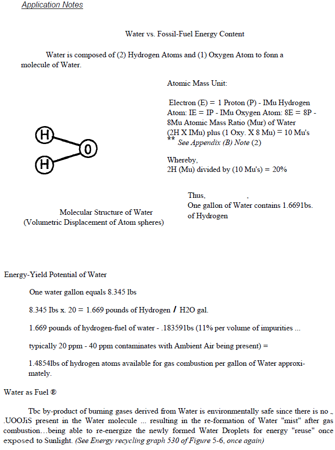
The logical alternative fuel source is water.
Most people do not realize that when you burn gasoline you are actually burning hydrogen contained within the fuel.
Water contains two and a half times more hydrogen by atomic weight than gasoline.
According to National Bureau of Standards data the energy released by hydrogen combustion is about 2.5 times greater than gasoline.
Therefore if we could efficiently release hydrogen from water we could solve both the energy crisis and the environmental pollution problem.
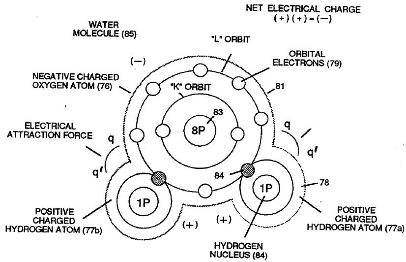
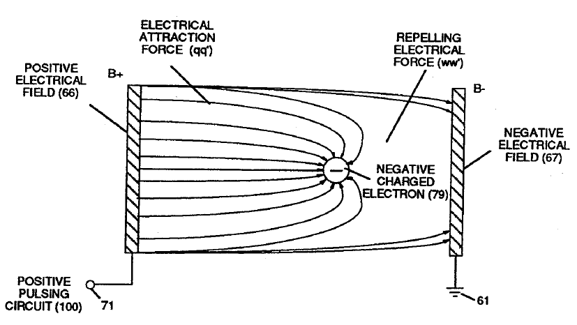
Figure 7 – Electrically Charged Water Molecule
(13:06)
The key question became:
How do we separate the water molecule in a physical manner rather than a chemical one?
Water molecules consist of hydrogen and oxygen atoms joined by electrovalent bonding.
When opposite voltage potentials are applied to the molecule the charged atoms can be pulled apart.
Figure 8 – Voltage Dynamics
(15:01)
By applying electrical stress of opposite polarity and restricting current flow we can physically separate the water molecule.
This process is called the electrical polarization process.
Figure 9 – Electrical Polarization Process
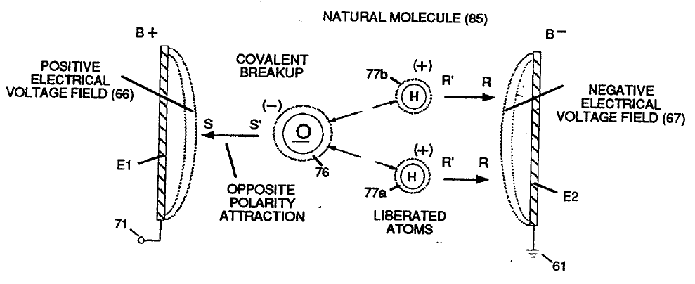
(15:59)
Three things occur simultaneously when separating the water molecule:
- The molecule elongates.
- Electron sharing between atoms changes.
- Covalent bonding collapses.
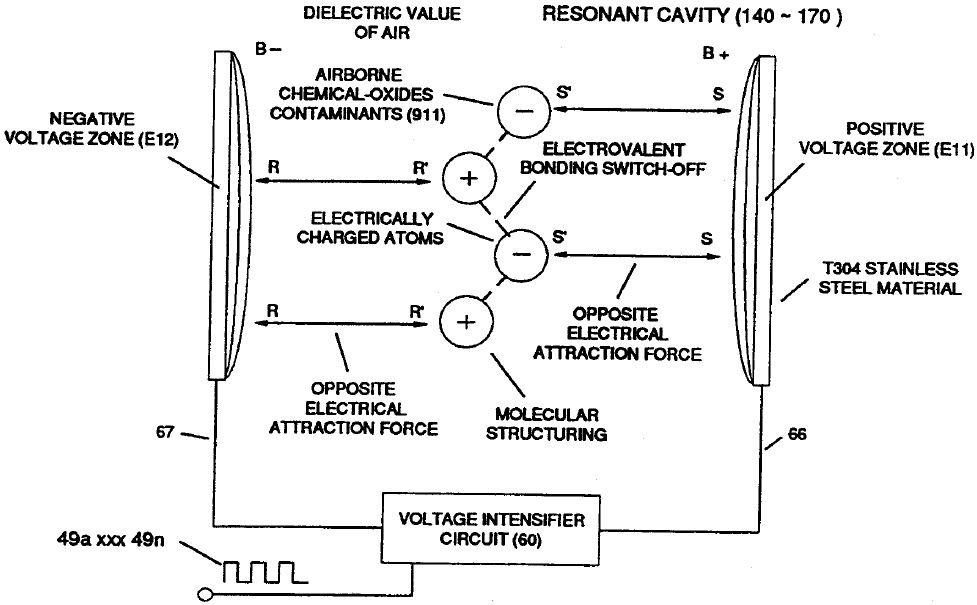
Figure 10 – Covalent Bond Shutoff
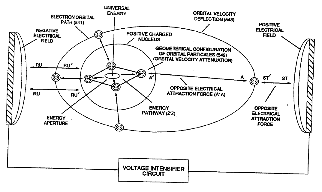
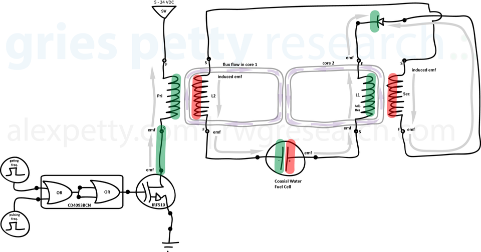
Figure 11 – VIC Impedance Network
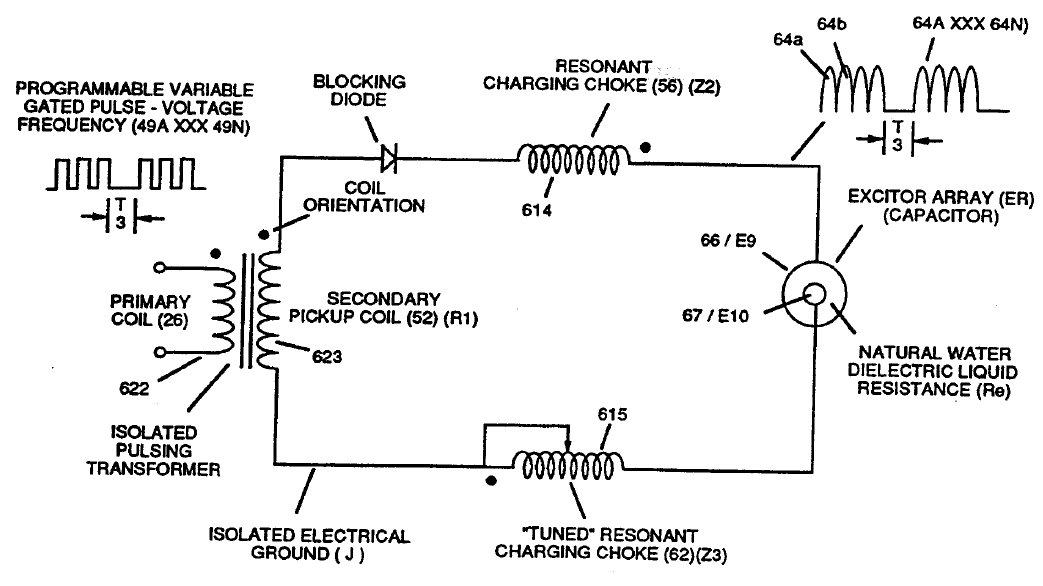
(18:26)
From this discovery it became clear that the electrical polarization process could be implemented using an electronic circuit.
This led to the development of what I call the Voltage Intensifier Circuit, or VIC.
In this design the dielectric value of water becomes part of the electronic circuit itself.
Two resonant coils are placed on either side of the water capacitor. The water acts as the dielectric medium between two voltage zones. By tuning the circuit to the dielectric characteristics of water we create a pulsing resonance condition.
When the circuit is tuned properly, voltage across the plates increases while current flow is restricted. This allows the electrical polarization process to separate the water molecule in a purely physical manner.
Figure 13 – Bifilar Amp Inhibiting Circuit
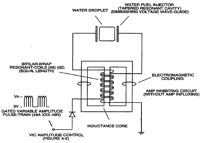
(19:16)
The resonant coils are wound in a bifilar configuration.
This arrangement further restricts current flow and enhances the voltage potential across the water capacitor.
The objective is always the same:
Allow voltage to perform the work while minimizing current consumption.
Figure 14 – VIC Coil Assembly
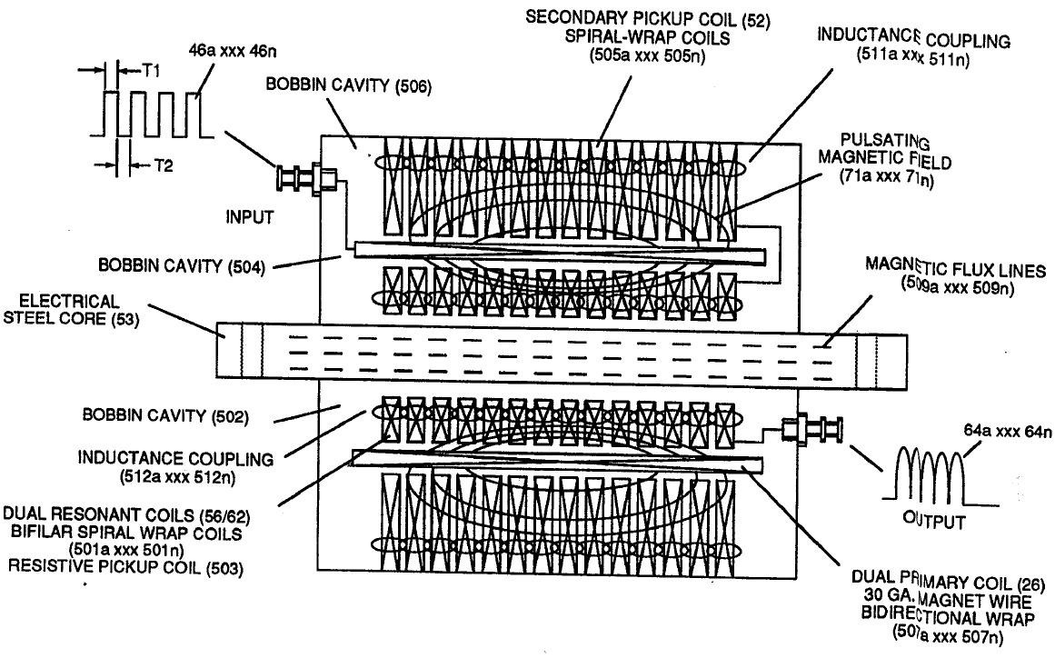
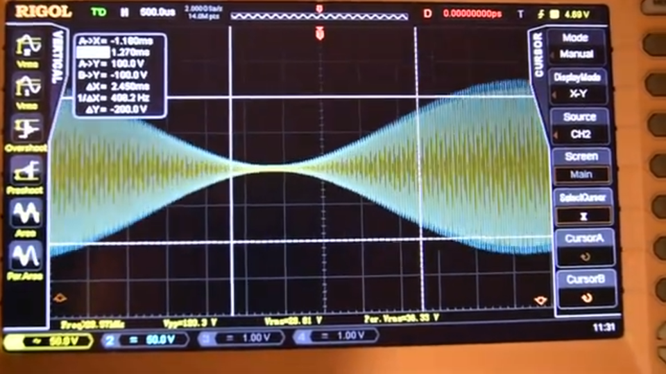
Figure 15 – Voltage Charging Effect
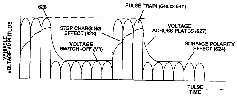
(19:28)
During system testing we observed that increasing the voltage resulted in a greater rate of hydrogen gas production.
Unlike electrolysis, which increases gas production linearly with current, this process produced non-linear increases in gas output as voltage increased.
Figure 16 – Resonant Cavity Water Fuel Injection
Figure 17 – Thermal Energy Yield vs Water Purity
(19:39)
We also discovered that the electrical polarization process works in all forms of natural water.
Even distilled water will respond to the process.
Figure 18 – Ionization Stage
(19:49)
The invention of using water as fuel was developed from the perspective of a businessman.
Under the law of economics, the method that wins is always the one that accomplishes the goal at the lowest cost.
Many catalytic approaches have been proposed, but they do not comply with economic practicality.
This technology was also developed using the KISS principle:
Keep It Simple, Stupid.
Once the mechanism of the water molecule was properly understood, the solution became straightforward.
Figure 19 – Triggering Resonance
Figure 20 – Sustaining Resonance
Figure 21 – Resonant Propagation
(20:41)
By tuning into the dielectric resonance of water we enter an atomic resonance condition.
This resonance propagates through the system and dramatically increases hydrogen production compared with conventional electrolysis.
Figure 22 – Energy Yield Under Resonance
Figure 23 – Burn Rate Control Method
Figure 24 – Alternate Burn Rate Control Method
(21:03)
Another key problem was learning how to adjust the burn rate of hydrogen.
Hydrogen normally burns at approximately 325 centimeters per second, which is far too fast for conventional internal combustion engines.
In order to retrofit existing engines we had to reduce that burn rate so that it matched the characteristics of fossil fuels.
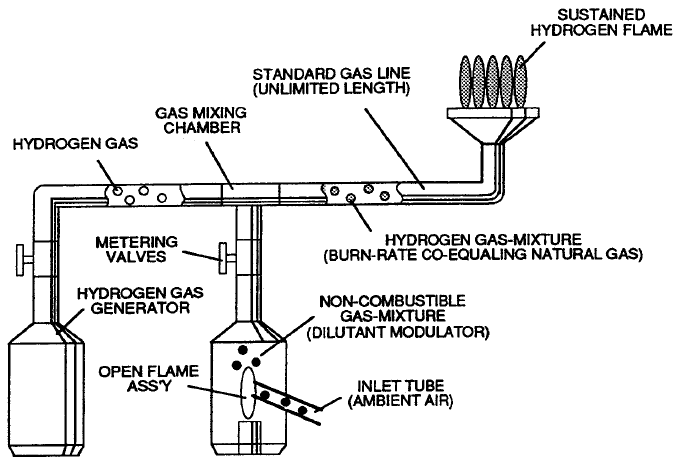
Figure 25 – Adjusted Hydrogen Flame

(21:33)
This diagram shows a hydrogen flame adjusted to approximately 37 centimeters per second.
By mixing hydrogen with non-combustible gases such as nitrogen and argon we can regulate combustion speed.
This discovery allowed the technology to be retrofitted to existing engines.
Figure 26 – Burn Rate Control Example
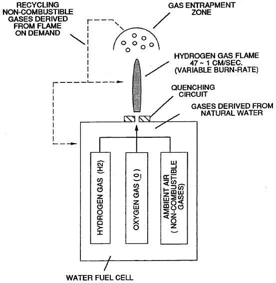
(21:54)
Water naturally contains dissolved ambient air.
When the water molecule is separated the released gases include both hydrogen and these non-combustible gases.
This automatically moderates the burn rate.
Water therefore acts as its own gas mixing regulator.
Figure 27 – Spark Arresting Process
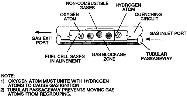
Figure 28 – Quenching Nozzle
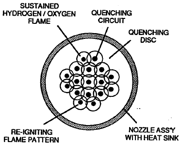
Figure 29 – Quenching Tube
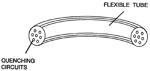
(24:03)
These components prevent flashback by separating hydrogen and oxygen gases within the delivery system.
This provides a reliable spark arresting mechanism.
Figure 30 – Spark Ignition Tube
(24:10)
By combining hydrogen with non-combustible gases we can match the burn rate of natural gas or gasoline.
This discovery made it possible to retrofit the technology to virtually any combustion engine.
Figure 31 – Burn Rate Comparison Table
(24:43)
This invention enabled us to retrofit existing engines using ordinary water as the fuel source.
The byproduct of combustion is simply water vapor, eliminating the emission of chemical oxides associated with fossil fuels.
Figure 32 – Recycling Flame Gases
(25:21)
We also had to adjust the burn rate down from the 5,000-degree flame shown earlier.
You have to be practical about these things. If you were to put that type of flame on a stove and your wife wanted to cook something, you would burn holes right through the pots and pans.
So the burn rate had to be reduced and controlled.
Figure 33 – Water Fuel Cell Retrofit for Internal Combustion Engines
(25:46)
This discovery allowed us to develop the technology necessary to operate a conventional internal combustion engine using water.
From an engineering standpoint the internal combustion engine can be viewed in three ways:
- It is a mechanical drive device.
- It is essentially an air pump.
- It is also a producer of non-combustible gases.
Air enters the engine, passes through the combustion chamber, and exits through the exhaust.
Because combustion occurs at relatively low temperatures compared with plasma conditions, the non-combustible gases in air do not significantly affect the combustion process.
By electronically meter-mixing these gases back into the hydrogen fuel we can precisely control the burn rate.
Under the law of economics, air costs nothing.
Rainwater costs nothing.
So the fuel source remains essentially free.
Figure 34 – Gas Grid Network
(26:48)
Another major development was the ability to transport hydrogen through existing gas distribution systems.
Conventional thinking suggested hydrogen must be cooled to extremely low temperatures, compressed, and transported under pressure.
However, by mixing hydrogen with ambient air and adjusting the burn rate to match natural gas, hydrogen can be transported through existing gas grid systems without changing a single valve.
Figure 35 – Hydrogen Fracturing Process Prior to Ignition
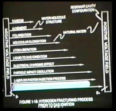
(27:21)
Developing a method for splitting the water molecule was only part of the challenge.
The real issue was maintaining the industrial economy.
During the Arab oil embargo I attended a meeting with industrial leaders in Ohio. The Columbia Gas system informed us that natural gas supplies were being cut off completely.
Without energy:
- factories stop producing products
- profits disappear
- companies fail
The larger the company, the faster it collapses.
(29:05)
This revealed a much larger strategic issue.
During the embargo the United States had only about two and a half days of fuel reserves for global defense.
Today that reserve is closer to one day.
When reserves fall that low the military must make difficult strategic decisions regarding global defense.
This situation demonstrated the urgent need for an alternative energy source.
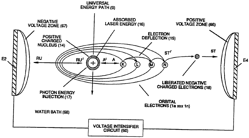
Figure 36 – Electron Extraction Circuit
(30:47)
This research led to the development of the electron extraction circuit.
In this circuit electrons are pulled from the water molecule during the polarization process. The extracted electrons generate electrical power which can sustain oscillation within the system.
Figure 37 – Destabilizing Combustible Gas Ions
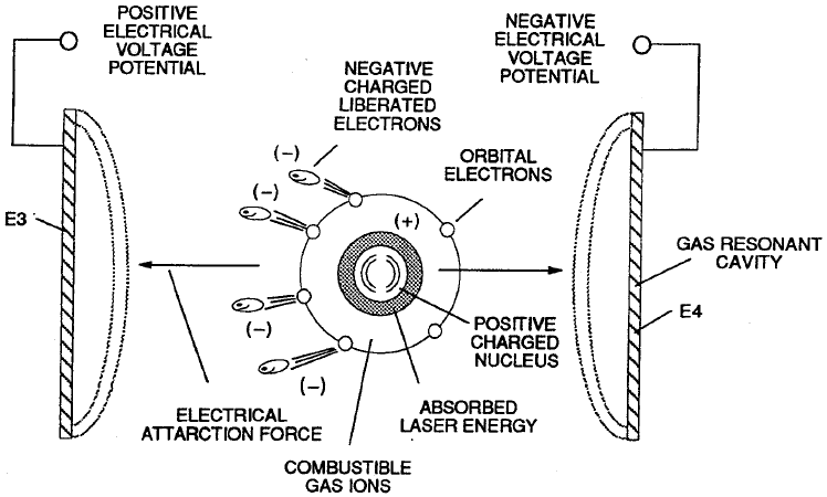
(31:11)
Once electrons are removed and photon energy is added, the atoms are brought to a sub-critical state.
Igniting the gases in this state releases a large amount of energy. This process is referred to as hydrogen fracturing technology.
Figure 38 – Stable Atomic Energy State
(32:45)
The Lord once said:
“We have eyes but we do not see.
We have ears but we do not hear.”
Consider natural phenomena such as hurricanes and lightning storms.
Electrical charges within the atmosphere cause water molecules to flex and release enormous energy.
The same principle can be applied intentionally through electrical polarization.
(33:39)
Einstein demonstrated that energy and mass are related through the equation:
E = mc²
Energy entering our universe forms matter and sustains life. If we understand how to trigger this process within atoms, enormous energy sources become available.
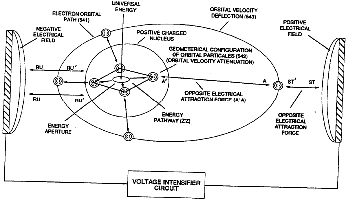
Figure 40 – Atomic Energy Aperture
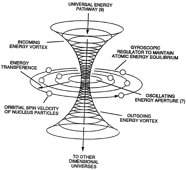
(39:17)
When atoms are subjected to electrical stress their internal particle structures slow down.
This creates an energy aperture through which additional energy can enter the atomic system.
Figure 41 – Oxygen Energy Balance
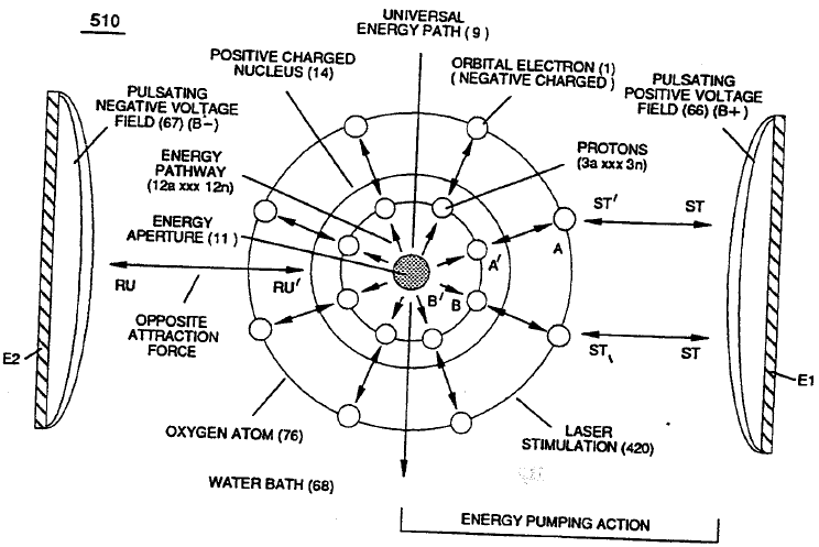
Figure 42 – Hydrogen Energy Balance
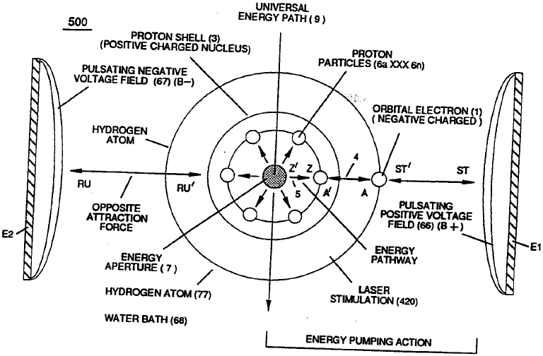
(40:15)
Each electrical pulse increases the energy stored within the hydrogen and oxygen atoms.
When the electrical stress is removed the stored energy becomes available as usable work.
This is the mechanism by which energy can be extracted from the water molecule.
Figure 43 – Energy Pumping Action

(41:03)
By repeatedly oscillating the atoms under electrical stress we pump energy into the system.
Igniting the gases at any point releases this stored energy.
This provides a potential method of powering vehicles, machinery, and industrial equipment using water as the energy carrier.
Figure 44 – Hydrogen Fracturing Process
Figure 45 – Hydrogen Fracturing Process (Alternate)
(42:24)
This is the point in the technology where we enter what I call the hydrogen fracturing process.
At this stage the atoms of the water molecule are taken to a sub-critical state. Electrons are extracted from the atoms while photon energy is introduced, raising the atoms to a highly energized condition.
In universities this type of behavior has been demonstrated in the muon process, where a hydrogen atom temporarily accepts a muon particle and releases large amounts of energy when the muon decays.
In our case we achieve a similar effect by extracting electrons and stressing the atom electrically.
When the hydrogen and oxygen atoms attempt to recombine into a water molecule the resulting collapse releases a large amount of energy.
The projected energy yield is estimated to reach millions of barrels of oil equivalent per gallon of water.
Figure 46 – Voltage Triggering
(44:02)
Of course we do not need to reach those extreme levels of energy release.
The key point is that the process can be controlled.
Once we understood the atomic mechanism we were able to engineer a system that converts water directly into usable thermal explosive energy.
Figure 47 – Tapered Resonant Cavity (Water Fuel Injector)
(44:52)
From this work we developed the water fuel injector, which replaces the conventional spark plug in an engine.
The injector exposes water to high voltage pulses inside a resonant cavity. This stretches the water molecule under electrical stress before ignition occurs.
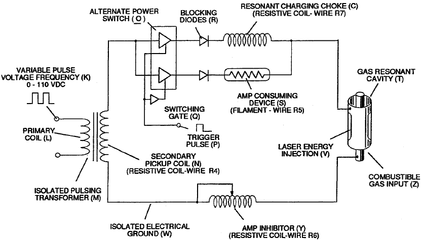
Figure 48 – VIC Circuit
(46:28)
The Voltage Intensifier Circuit provides the pulsed high voltage necessary to perform this process.
With the VIC circuit in place the spark plug can be replaced entirely by the water fuel injector.
Figure 49 – Dynamic Voltage Potential
Figure 50 – Resonant Cavity Geometries
(46:34)
Different resonant cavity geometries can be used.
A tapered cavity produces a compressional wave effect, while other geometries allow the thermal energy to be directed at various angles.
This flexibility allows the system to be adapted to many different types of engines.
Figure 51 – Water Fuel Injection System
Figure 53 – Water Fuel Management System
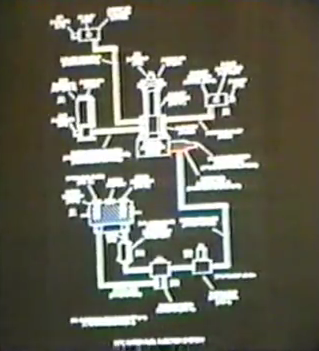
(46:59)
The final system design is quite simple.
Water is meter-mixed into the injector, exposed to high voltage pulses, and the resulting energy release powers the engine.
Figure 54 – Water Fuel Injection Kit
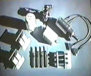
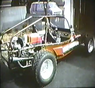
Figure 55 – Water Fuel Injectors Installed on the Dune Buggy
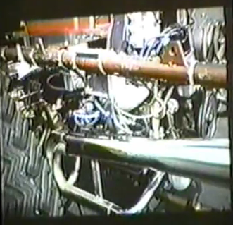
Figure 56 – EEPROM-Based Controller
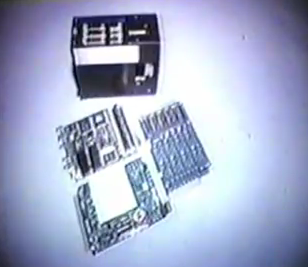
(47:27)
Modern electronics allow the entire control system to be miniaturized using EEPROM technology.
This dramatically reduces cost and complexity.
Figure 57 – Gas Processor
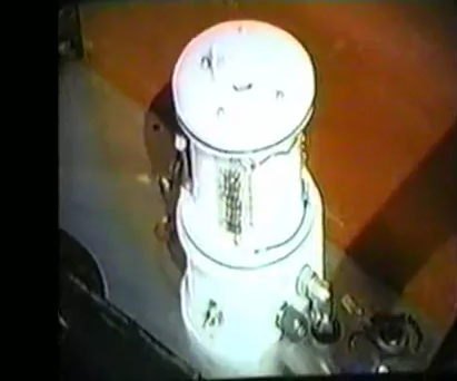
Figure 58 – Meyer’s Water-Powered Dune Buggy
(47:40)
The gas processor ionizes ambient air and helps purify exhaust emissions.
Instead of polluting the air, the system can actually help restore atmospheric balance.
Figure 59 – Steam Resonator

(48:02)
Another question people ask is what happens during cold weather.
To solve this we developed the steam resonator, which heats the water through molecular oscillation using electrical pulses.
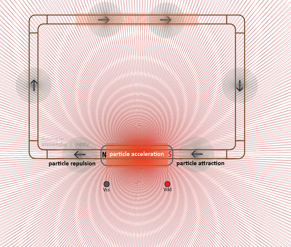
Figure 60 – Particle Oscillation Energy Generator
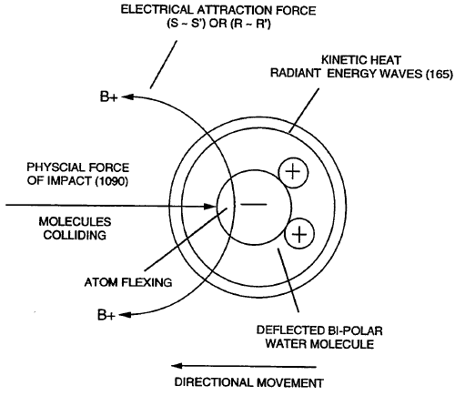
Figure 61 – Atomic Energy Level Adjustment
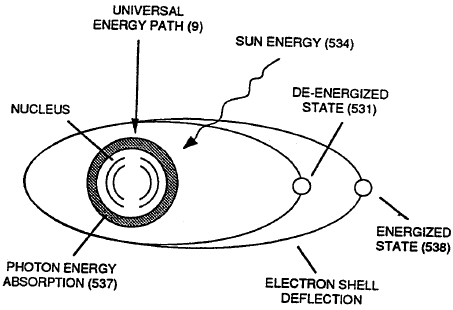
Figure 62
(48:12)
By stretching and releasing the water molecule we create heat through particle oscillation, preventing freezing and providing additional useful energy.
Figure 63 – Air Reclaimer Technology
(48:34)
The technology also enables electrical power generation.
Under the U.S. National Security Energy Act of 1992, any retrofit fuel system must be oxygenated.
Our system uses the oxygen already present in water, making it compliant with the law.
Figure 64 – Solar Energy Rebalancing
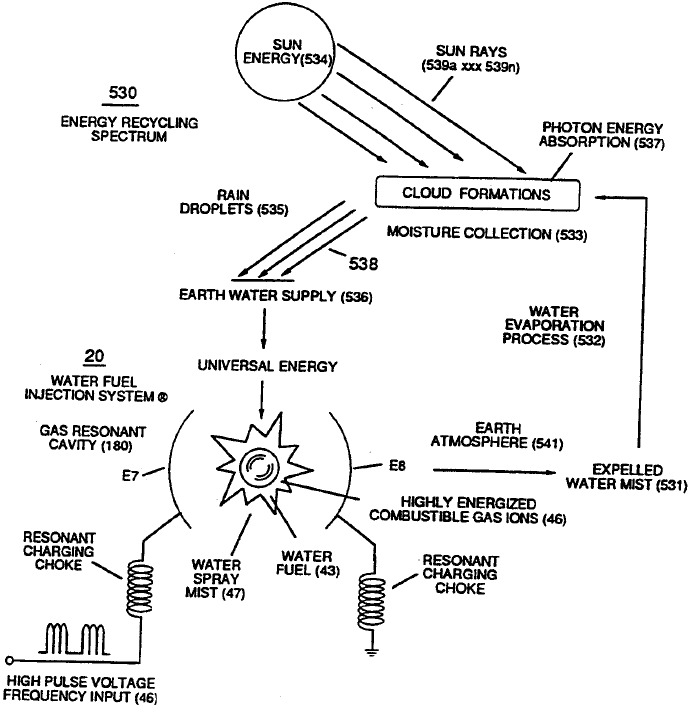
(50:13)
In many ways this system can be thought of as a solar device.
The sun supplies the photon energy that restores the energy state of water vapor emitted from the engine.
Figure 65
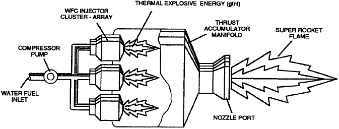
Figure 66
(51:06)
We are currently entering industrial contracting phases.
Many laboratories around the world have confirmed aspects of the technology, and discussions are underway regarding commercialization.
Figure 67 – “It will be brought in by the people”
(51:54)
Ultimately, however, it will not be one person who introduces this technology.
It will be people everywhere coming together to demand solutions to the energy and environmental problems we face.
Figure 68 – ASER Technology
(52:19)
Further developments include ASER technology, which oscillates hydrogen atoms under electrical stress and may lead to extremely powerful laser systems.
Figure 69 – Jet Engine Retrofit
(52:52)
Jet engines can also operate using water fuel technology by electronically controlling the burn rate to match combustion chamber conditions.
Figure 70 – History in the Making

(53:22)
Any questions?
(Applause)
Q&A
(53:32)
Question: If you start with a gallon of water in a closed system, how much water remains at the end?
Answer:
In our tests the same amount of water remains. The atomic structure is not destroyed; the water molecule is simply cycled through energy states.
(54:31)
Question: When will production retrofit kits be available?
Answer:
Several projects are currently about 90–95% complete. Assuming no major interference, production units could be available within one to two years.
(55:38)
Question (Eugene Mallove):
Would you allow independent testing of the system?
Answer:
Many laboratories have already tested aspects of the technology. However, releasing full system details publicly before patents are secured could jeopardize development rights.
(1:00:33)
Thank you very much.
(Applause)
.:.