Water as Fuel with Puharich and Meyer
Water is one of the most abundant substances on Earth. More than 300 million cubic miles of it cover the planet’s surface.
Chemically, water consists of two hydrogen atoms bonded to one oxygen atom. When hydrogen and oxygen gases are burned together they produce water as their exhaust.
This leads to an obvious puzzle.
If water is already the exhaust product of hydrogen combustion, how could it ever be used as a fuel?
Conventional electrolysis provides the standard answer: electrical energy can split water into hydrogen and oxygen gases. Those gases can then be burned to produce energy.
The difficulty is that electrolysis typically requires more energy input than the combustion of the resulting gases can return. In other words, water splitting is normally an energy-consuming process rather than an energy-producing one.
Because of this limitation, water is generally not considered a practical fuel.
However, during the late 20th century a small number of inventors began exploring unconventional electrical methods for interacting with the water molecule. Their aim was to determine whether the covalent bonds holding the molecule together could be disrupted using high voltage and very low current electrical fields.
One of the earliest patents along these lines was filed by Dr. Andrija Puharich.
Interestingly, when Puharich filed his patent in June of 1981 he lived only a few miles from where I live today.
His patent, granted July 19, 1983, was titled:
“Method and Apparatus for Splitting Water Molecules.”
You may review the patent here:
< /content/images/2010/09/US4394230.pdf >
Puharich’s Approach
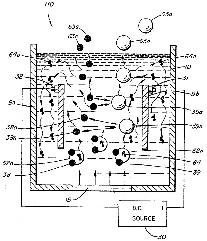
Puharich’s apparatus consisted of several elements arranged in series:
- Electronics used to generate and control the waveform
- An isolation transformer
- A capacitor formed from insulated cylindrical plates using water as the dielectric
- Inductors placed on either side of the water capacitor
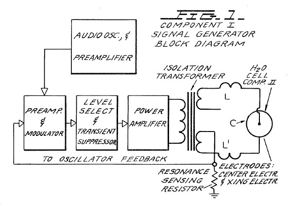
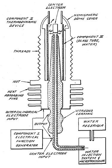
The water fuel cell itself was arranged as follows:
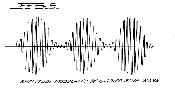
Puharich energized the system using a low-frequency amplitude-modulated AC waveform.
Typical parameters were:
- modulation frequency: 20–200 Hz
- carrier frequency: 200 Hz – 100 kHz
The system was tuned so that the water capacitor became resonant with the Vss-side inductor.
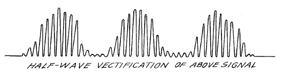
As the electrical polarization of the water increased, the water between the plates acted as a nonlinear element that partially rectified the incoming waveform.
Meyer’s Development
Shortly after Puharich’s patent was granted, Stanley Meyer began pursuing similar ideas.
I cannot say with certainty whether Meyer’s work began after reading Puharich’s patent. However, the similarities between the two approaches and the timing of the patent filings suggest that Meyer was at least aware of Puharich’s work.
From 1983 until his death in 1998, Meyer received more than fifteen patents describing variations of his water fuel cell system.
One of the most detailed descriptions appears in his 1990 patent, which may be reviewed here:
< /content/images/2010/09/US4936961.pdf >
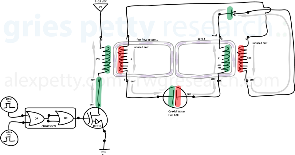
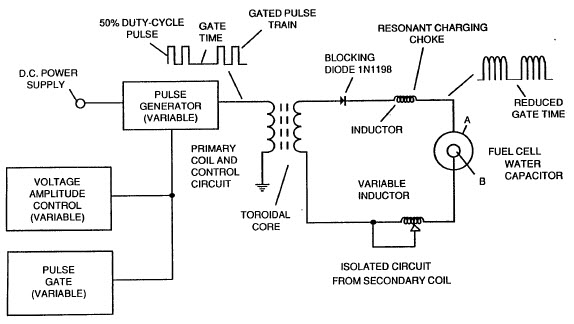
Like Puharich’s design, Meyer’s system used a series arrangement of:
- waveform control electronics
- an isolation transformer
- a water capacitor formed from stainless steel coaxial tubes
- inductors placed on either side of the capacitor
Meyer also added a blocking diode on the Vdd side of the circuit.
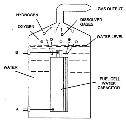
The water fuel cell itself consisted of coaxial stainless steel tubes arranged as a cylindrical capacitor.
Meyer’s Waveform Strategy
Unlike Puharich, Meyer used two square-wave signals:
• a high-frequency signal tuned to the resonant frequency of the cell
• a low-frequency gating signal used to periodically interrupt the resonance
The gating interval allowed the electric field within the cell to collapse before the next burst of pulses.
The resulting waveform appears as a series of resonant pulses followed by an off period.
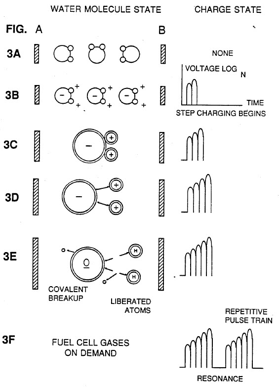
According to Meyer, this process causes the voltage across the water capacitor to increase in a step-charging manner.
As the electrostatic field grows stronger, the water molecules become increasingly polarized and eventually separate into hydrogen and oxygen gases.
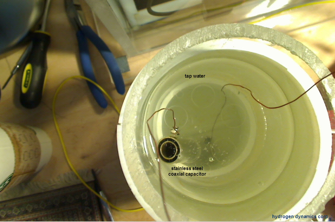
My Experimental Setup
In an attempt to better understand Meyer’s claims, I constructed a water capacitor similar to the one described in his patents.
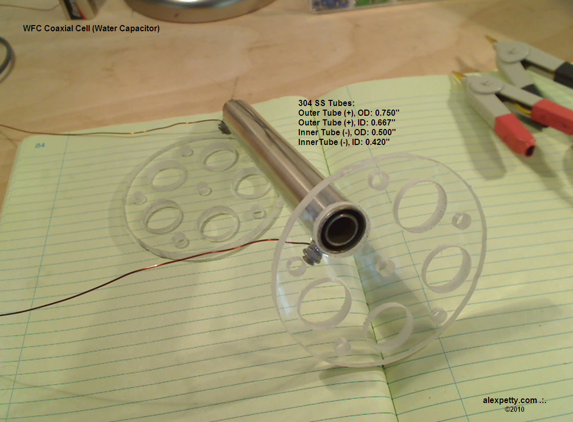
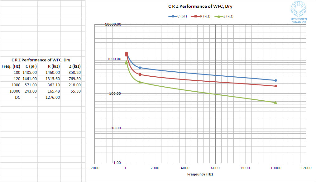
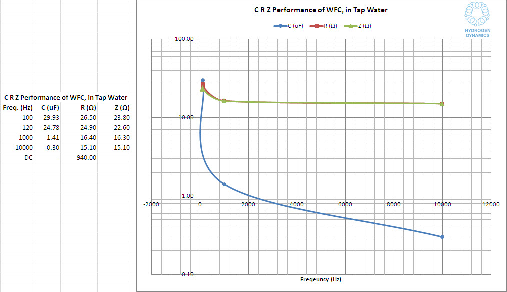
I then measured the electrical characteristics of the capacitor both dry and submerged.
The cell mounted in water is shown below.
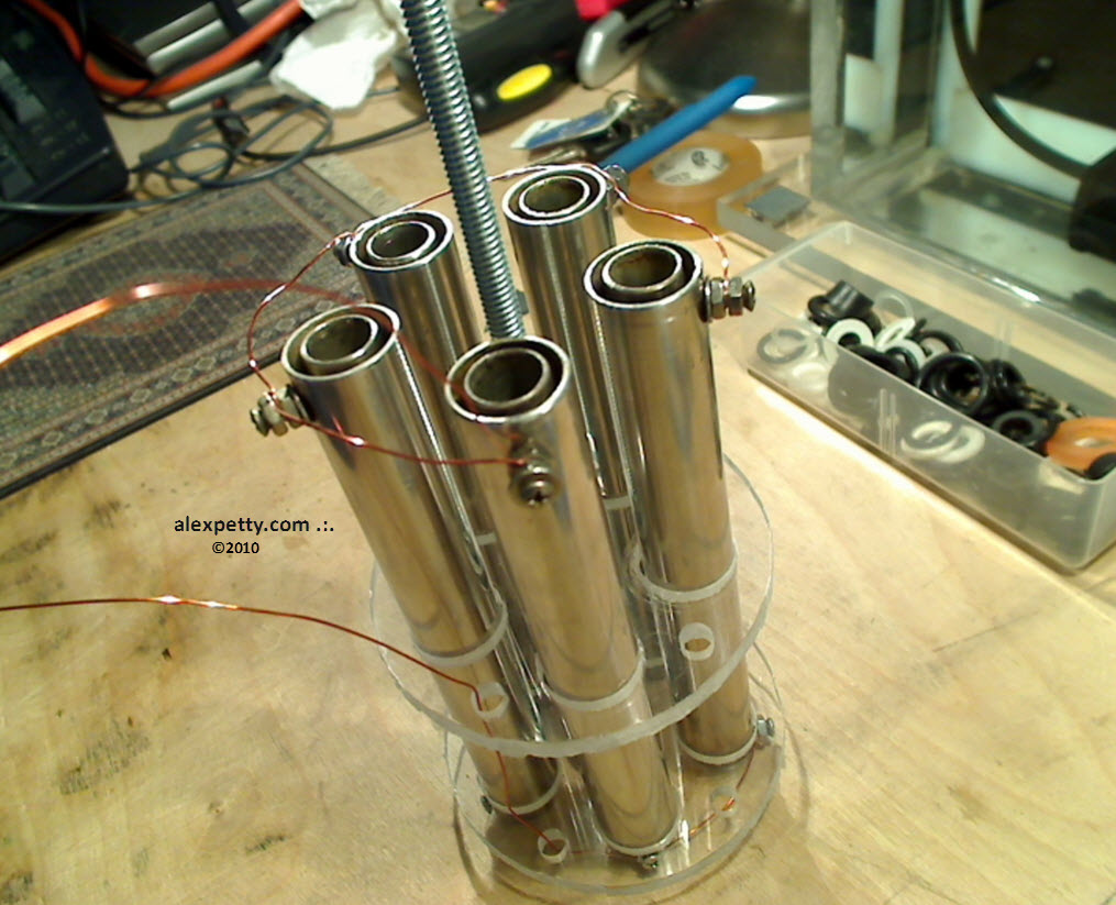
I also constructed a five-capacitor array.
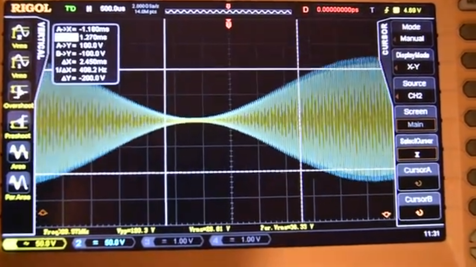
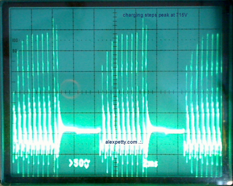
The circuit was driven using a pulse frequency of 2110 Hz with a gating frequency of 120 Hz.
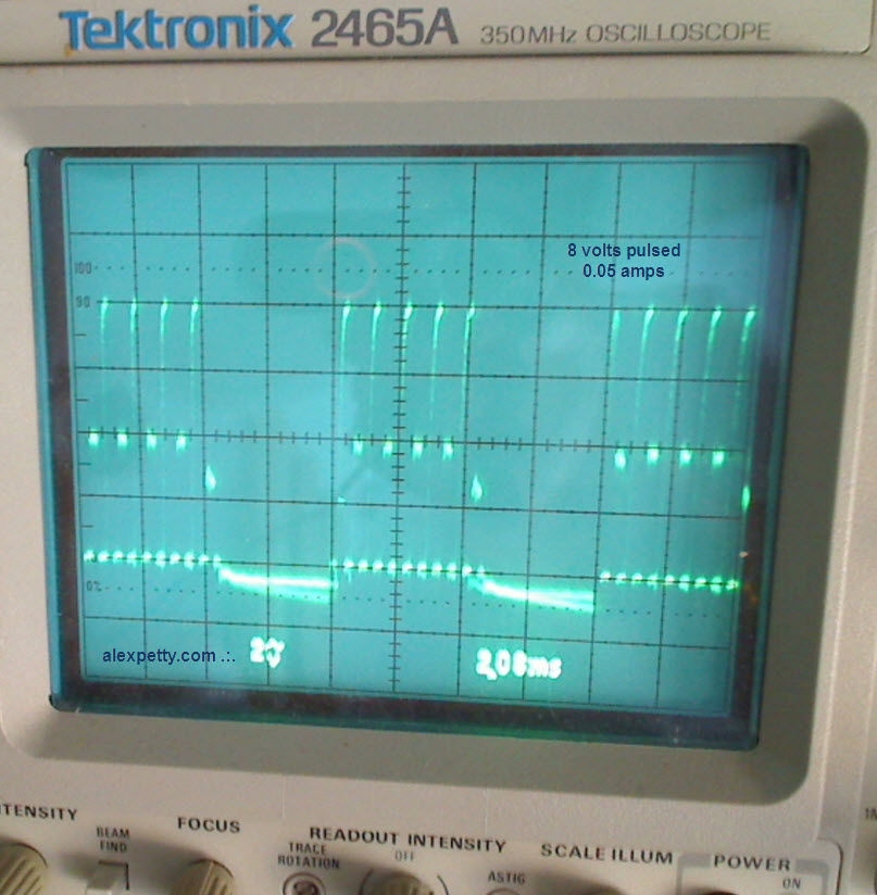
The resulting waveform measured across the water capacitor appears below.
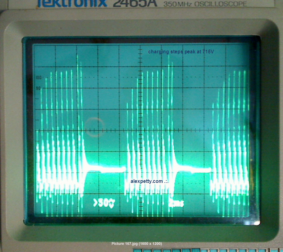
During this test the step-charging effect reached approximately 715 volts across the cell.
The system produced very small quantities of gas while consuming approximately 1500 mW of electrical power.
Observations
The experiment does appear to demonstrate that gas can be produced using a high-voltage / low-current approach, similar to the method described in Meyer’s patents.
However, without precise calorimetric measurements it is difficult to determine whether the process yields more energy than it consumes.
My own expectation is that the energy recovered from burning the resulting gases would likely be less than the energy required to produce them.
Nevertheless, given Meyer’s claims and the reported operation of his water-powered dune buggy, it would be worthwhile for someone with proper laboratory equipment to perform careful thermodynamic measurements on such systems.
Only then could the question of true efficiency be answered definitively.
.:.